Part I Control Center Management Concepts
Part I of this guide provides a general overview of Control Center management concepts and the Control Center application.
Part I of this guide contains the following chapters.
Chapter 1 Control Center Management Overview
This chapter includes a high-level description of Infrastructure Fabric (I-Fabric) components, the N1 Provisioning Server software and server Farms. This chapter also describes application components and account administration tasks.
This chapter includes the following topics:
Overview
This section provides a brief overview of the I-Fabric components and the N1 Provisioning Server software. For a detailed description, please refer to the N1 Provisioning Server 3.1, Blades Edition, System Administration Guide.
An I-Fabric (Infrastructure Fabric) combines computing, storage, and networking resources into a contiguous infrastructure that you deploy and repurpose to meet changing requirements. An I-Fabric is controlled and managed by the N1 Provisioning Server Software.
I-Fabric Components
An I-Fabric integrates otherwise individual, heterogeneous networks, servers, storage, and infrastructure devices into a coordinated, automated fabric. This fabric enables easy management, deployment, and redeployment of logical server farms. An I-Fabric is made up of three functional areas:
-
Control plane – The control plane consists of the N1 Provisioning Server software and the associated server hardware on which the software is deployed.
-
Fabric layer – The fabric layer contains the networking infrastructure and switching fabric. This layer enables the software in the control plane to dynamically create, manage, and change the networking and security boundaries of logical server farms.
-
Resource layer – The resource layer consists of infrastructure resources such as blade servers and load balancers. The resource layer of an I-Fabric contains the infrastructure resources you may provision to logical server farms.
The control, fabric, and resource layers work together to dynamically create logical server farms. A logical server farm is the fundamental structure deployed and managed within an I-Fabric. The N1 Provisioning Server software allocates logical server farms from the pool of resources available within the resource layer. Secure partitions enforced by the software and methodologies enable you to exercise independent administrative control over each logical server farm. Although you can have administrative access on all devices within a logical server farm, you cannot view, access, or modify the devices or data associated with a different logical server farm unless you have the appropriate permission.
The N1 Provisioning Server software provides a comprehensive set of infrastructure automation and management capabilities. The software comprises two primary components: the N1 Provisioning Server and the Control Center.
-
The N1 Provisioning Server is the core automation component and provides the interface between the Control Center and the physical infrastructure resources.
-
The Control Center is the web browser-based graphical user interface (GUI) that enables design, configuration, and ongoing management of logical server farms.
N1 Provisioning Server Software
The N1 Provisioning Server software provides the infrastructure automation services required to manage and deploy logical server farms within an I-Fabric. The N1 Provisioning Server software manages the logical-to-physical mappings between a logical server farm and the physical resources that are assigned to the server farm.
The N1 Provisioning Server software contains the following software subsystems.
-
Control plane database (CPDB), which is a persistent, central repository of data.
-
The image server, if you have a local storage configuration, which manages images. The image server can be either an NFS or an FTP file server. The image server can run on an control plane server or on a stand-alone server.
-
Monitoring software, which monitors the health and state of an I-Fabric and the logical server farms within.
The Control Center is the user interface to the control plane software from which you deploy and manage logical server farms. The Control Center is the primary farm management tool. See Chapter 2, Control Center Application Overview for an overview of the Control Center Management GUI.
Farm Lifecycle
The N1 Provisioning Server software uses the concept of a farm lifecycle as a means for managing farms.
All requests for creating and activating a new farm, or requests for changes to an existing farm, are sent from the Control Center or the command-line tools.
Note –
Refer to N1 Provisioning Server 3.1, Blades Edition, System Administration Guide for a detailed description of various components and functions of the N1 Provisioning Server software.
The state of the farm determines which administration task is required.
Farm States
The farm lifecycle is defined by various states. The lifecycle state of a farm is displayed graphically in the State Diagram icon as shown in the following illustration. The State Diagram icon is used throughout the Control Center to indicate farm lifecycle state.
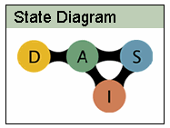
The farm lifecycle icon is displayed with a red circle to indicate the state of the farm. The following sections describe the four possible states of a farm.
Design Farm State
The design farm icon indicates a new, blank farm. This icon could also describe a farm that was created and saved through the Control Center but has not been submitted for approval and activation. This situation is similar to a paper design of the farm. The farm does not yet exist in the control plane database (CPDB). No hardware, storage, or network resources are deployed at this stage. During this phase, users can configure farm elements. Because no resources are actually allocated, any number of farms can exist in the design phase.
Active Farm State
The active farm icon indicates that the farm is activated and is running. Upon activation, IP addresses are available and users can perform additional configuration and load software images. The following Service Processor states are possible for an active farm: ACTIVE, IDLE, BACKUP, UPDATED, WIRED, and DISPATCHED.
A farm design that is submitted for activation awaits approval and subsequent activation by an administrator. Place your cursor over the icon to see that the icon is labeled pending activation to reflect the transition state.
Standby Farm State
The standby farm icon indicates that all farm elements (excluding local storage) are returned to the free pool. Because storage and farm network configuration is preserved, a farm can be rapidly reactivated. The following Service Processor states are possible for an active farm: STANDBY.
When an active farm is set to standby, farm awaits administrator action. Place your cursor over the active icon to see that the icon is labeled pending standby.
Inactive Farm State
The inactive farm icon indicates that the farm is inactive and all hardware resources (including storage) are returned to the free pool. The farm cannot be reactivated. However, you can make a copy of the design and subsequently activate the design. The following Service Processor states are possible for an active farm: DEACTIVATED
When an active farm or a farm on standby is made inactive, the farm awaits administrator action. Place your cursor over the icon to see that the active icon is labeled pending inactive.
Service Processor States
The internal farm state as maintained by the Service Processor is only visible to you through the Service Processor command-line interface. These internal states help you monitor the progress of a farm through the various stages of automated activation, updates, and decommissioning. These internal states help you troubleshoot problems if necessary. These states are described in Table 1–1.
Note –
See the N1 Provisioning Server 3.1, Blades Edition, System Administration Guide to learn how to access this information through the command-line interface. Some of these states do not typically occur during the normal farm lifecycle and are used for special administrative purposes only.
Table 1–1 Internal SP State
|
Service Processor State |
Control Center State |
Description |
|---|---|---|
|
CREATED |
Design |
The farm has just been created but not submitted for activation. |
|
NEW_CONFIG |
Design |
Same as CREATED in terms of farm resource changes, but the Service Processor has now taken over the farm. |
|
ALLOCATED |
Design |
Resources are allocated to the farm in the database. |
|
WIRED |
Design, Active |
Physical devices are connected according to the farm topology. |
|
DISPATCHED |
Design, Active |
A Service Processor owns the farm. Domain Name System (DNS), Dynamic Host Configuration Protocol (DHCP), and Network Interface Card (NIC) are set up for the farm. Farm monitoring is also registered or in the process of registering at this stage, if applicable. This stage is part of both the initial activation process and the farm update process. |
|
ACTIVE |
Active |
The farm is active and running. |
|
IDLE |
Active |
A Service Processor does not own the farm. The farm might be active as before. No communication between farm devices and the Service Processor is allowed. |
|
STANDBY |
Standby |
The farm is on standby. IP addresses and disks are still associated with the farm. |
|
SHUTDOWN |
Active (pending standby or inactive) |
The farm devices are shut down. |
|
UNWIRED |
Active (pending standby or inactive) |
Physical devices are detached from the farm. |
|
DEACTIVATED |
Deactivated |
The farm is deactivated and all resources are freed. |
|
UPDATED |
Active |
The farm has been updated. |
Chapter 2 Control Center Application Overview
Use the various screens in the Control Center to perform most farm management tasks, such as setting up accounts, building and activating farms, setting up monitors, and so on. Understanding how to use these screens is a key factor in successfully managing farms. This chapter describes how to navigate the major Control Center screens.
This chapter includes the following topics:
Control Center Concepts
The Control Center is a web-based user interface for the N1 Provisioning Server software. The interface provides for the automated deployment, management, and control of heterogeneous computing environments. The Control Center enables you to design, configure, deploy, and manage multiple independent, secure, logical server farms.
The visual, drag-and-drop interface enables you to express complex network topologies, add and remove hardware, and configure farm elements. You can also create libraries of farms and farm templates that enable rapid, standardized, and automated deployment of farms within a data center or across data centers.
For each new logical server farm you design, the Control Center enables you to do the following tasks:
-
Design arbitrary network topology, including subnet configurations
-
Configure and provision servers and load balancers
-
Create and distribute software images
Note –Although you can perform virtually every farm management task using the Control Center, you can also use command-line tools to perform these tasks if you choose to do so. However, farms that are created through the command-line interface do not appear in the Control Center.
The Control Center uses the concept of a farm lifecycle. The term "lifecycle" describes the process of managing the farm evolution from design to destruction.
-
Design a new farm by using one of the following methods.
-
In the Control Center Editor screen, connect network component icons and configure as appropriate for your business needs. See How To Design a New Farm.
-
Import an existing farm by selecting Import from the File menu in the Editor screen. See How To Import a Farm.
-
-
After you have designed a new farm, submit the design for activation. The network, devices, and storage are provisioned and configured according to your specifications in a very short time, as little as ten minutes, depending on the complexity of your design.
-
After the farm is active, you can deploy server monitors and configure alarms. Monitors and alarms are important for farm maintenance and troubleshooting. See Setting Up Element Monitors and Alarms for detailed information. You can also add, remove, or reconfigure elements, servers, and images in an active farm as your business needs require. See Updating Active Farms for detailed instructions.
-
The standby option on the Control Center enables you to put your farm on hold, releasing the servers and load balancers for others in your organization to use. Your data is maintained for later reactivation while in standby. See Placing a Farm On Standby. When you are completely finished using a particular farm, you can elect to completely decommission the farm, returning all hardware and disk resources to a pool of free resources.
Access Privileges
To administer access privileges in the Control Center, you define access in terms of the user's level of authority and associated privileges. There are three classes of access privileges:
-
Administrator refers to individuals who manage an entire I-Fabric or multiple I-Fabrics, do not belong to any particular account, and have access and control over all accounts, including approval privileges.
-
Account Manager refers to individuals in an organization who manage their specific account and users within that account.
-
User refers to individuals in an organization who manage farms within that account but are limited in their ability to change account-wide settings or manage other users.
Farm Management Tasks
After the I-Fabric has been built and the N1 Provisioning Server software installed, you are ready to begin farm management tasks. Generally, as part of system acceptance, you also create global and account software images before you begin to build farms. For instructions on creating software images, refer to Creating and Managing Images in N1 Provisioning Server 3.1, Blades Edition, System Administration Guide.
Farm management lifecycle involves the following major tasks:
-
Creating Control Center accounts
-
Designing and configuring farms
-
Activating farms
-
Setting up farm monitors and alarms
-
Managing changes in farm states
-
Managing end-user accounts
Farm Management Responsibilities
In some I-Fabric implementations, end users design and configure farms, create monitors and alarms, and manage end-user accounts. In other I-Fabric implementations, administrators perform all farm management tasks.
This guide assumes that administrators perform all farm management tasks. However, this guide identifies those areas where end users can request administrative support.
Task Roles for Each Farm Lifecycle State
The Control Center supports various levels of access privileges. These access privileges enable end users, as well as administrators, to perform certain farm management tasks. In I-Fabric implementations that do not enable end users to interact with the Control Center, administrators perform all tasks.
Table 2–1 lists the various high-level tasks that need to be performed during each of the farm lifecycle states.
Note –
Administrators who are responsible for all farm management tasks perform all tasks listed in this table.
Table 2–1 Lifecycle States and Administration Tasks
|
User or Account Manager Tasks |
Administrator Tasks |
Lifecycle State |
|---|---|---|
|
New farm created but not yet submitted |
None |
Design |
|
The user submits the farm for approval and activation |
Manually validate the submitted farm. |
Activation |
|
|
Use the Administration screen to unblock the request, if the farm is valid. |
|
|
|
Set the contract parameters in the Control Center Administration screen. |
|
|
|
Turn over active farms to the users. |
|
|
Migrate application and data |
Work with users and assist in migration. |
Active |
|
Create server images |
Create global images, see Creating and Managing Images in N1 Provisioning Server 3.1, Blades Edition, System Administration Guide. |
|
|
Change or flex farms |
Changing farms is an automated process if the resources are within the set contract type limits. If a farm is not bound by a contract, the request must be unblocked. |
|
|
Submit a redesigned farm as new |
Same task as when the new farm was submitted. |
|
|
Request that all farm elements (excluding storage) be returned to the free pool. |
Unblock the standby request through the Administration screen. |
Standby |
|
Request reactivation |
Unblock the reactivate request through the Administration screen. |
|
|
Request deactivation |
Unblock the Deactivate request through the Administration screen. |
Inactive |
|
Delete the farm |
|
Deleted |
Control Center Accounts
A Control Center account contains a group of people, or account members, who have management access and control of a set of logical server farms. Accounts include the following information:
-
Login information and privileges for people authorized to manage farms in the account
-
Information on the organization or department that owns the account
-
Contract data (quotas) defining farm level resource limits
-
Collection of farms
-
Account Images
The Control Center can contain multiple accounts, each managed by Account Managers serving multiple users managing multiple farms, potentially spanning multiple I-Fabrics.
An individual with user access in a particular account can manage a farm or group of farms in secure isolation from users in other accounts. For more information regarding Control Center accounts, see Chapter 3, Account Administration.
Control Center Security and Certificates
The Control Center includes the security aspects described in the following list.
-
Authentication
Each user is assigned a username and a password that is used to authenticate the user during login. No format or restriction is placed on the password, except that the password must be a non-empty string.
Note –If an end user forgets the password, an administrator must reset the password to some known value. Retrieval of the password is not possible.
-
Brute-force password attacks
The Control Center defends itself against brute-force password attacks by using the authentication mechanism to keep track of login failures for each user. If any user has 10 consecutive failed logins, the user is placed in a “penalty box,” during which time the user cannot log in, even with the correct password. The user is automatically released from the lock after a short period of time. An administrator can release the lock ahead of schedule, if needed.
-
The Control Center is designed to run with 128-bit SSL encryption. This level of encryption provides security against eavesdroppers.
-
Session expiration
If a logged-in user is dormant for longer than a configurable period of time, the user is prompted to re-enter the username and password to ensure that the same person is returning to the client machine. The default session expiration is 120 minutes.
Security Certificate
A default security certificate is provided for the Control Center. This security certificate will expire after six months. To update this certificate or to install a new certificate see Sun ONE Application Server 7 Administrator's Guide to Security.
Control Center Component Overview
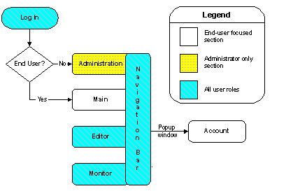
The Control Center Main, Editor, and Monitor screens require user access privileges. The Administrator screen and the N1 Provisioning Server command line interface require administrator access privileges. Figure 2–1 describes the different screens of the Control Center and the user roles required to access each screen.
Figure 2–1 Navigation Model
Main Screen
The Main screen is used primarily by end users whose management privileges and responsibilities are limited to a specific account and the related farms. This screen displays after you log into the Control Center. This screen provides a summary view of farms within the end user's account. This screen is also the starting point for various management tasks for those farms. Figure 2–2 shows the various areas of the Main screen.
You use the Main screen to do the following tasks:
-
Read news and messages
-
View farm status and configuration within an account
Figure 2–2 Control Center Main Screen

The Main screen gives you access to various features:
-
News and Messages
-
Farm Details
-
Farm Chooser
-
Farm View Area
Note –Only the latest known (stable) state of the farm is displayed in the Control Center Main screen.
News Details and Farm Details
The Farm Details and News Details window displays details of the Main screen feature with which you previously interacted. For example, if you clicked one of the items listed under the News Details previously, then the window displays the details for that item. If you clicked the Farm Chooser previously, then the window displays the farm details.
News and Messages
The News and Messages section provides links to useful information published by the administrators of the system. News and messages may be published globally or per account. When you click the link, the related article displays in the News Details section.
Note –
The Control Center administrator sets up the links in this window to provide users with a variety of information.
Farm Details
The Farm Details section displays the following information about the farm:
-
Name – The name of the farm in your account
-
State – The current state of the farm
-
Status – Monitoring feedback for the current farm displayed
-
I-Fabric – A set of managed infrastructure resources where the selected farm runs
-
Contract Type – Resource provisioning permissions for the farms and the type of contract (quota types) attached to the farm
-
Request History – The request history of the farm, that is, updates and changes to the farm
-
Resources – A graphical representation of the minimum and maximum limits and the current usage of various resources in the farm
Farm Chooser
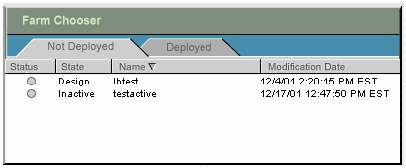
When a new account is created and first used in the Control Center, the Farm Chooser is empty. However, after you start designing and activating farms, you use the Farm Chooser to do the following tasks:
-
View topologies that are Not Deployed and Deployed.
-
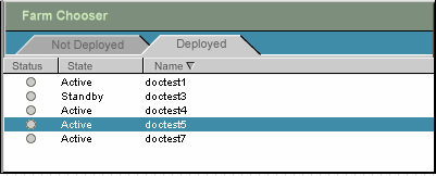
The Deployed view lists the farms that are Active or in Standby states
-
The Not Deployed view lists all other farms and includes those farms in Design and Inactive states
-
-
Check the state, status, and modification date of farms
The Farm Chooser lists the farms created by all users in the same account. Figure 2–3 shows an example of the Farm Chooser window.
Figure 2–3 Farm Chooser - Not Deployed
Farm View Area
Farms selected in the Farm Chooser are displayed in the farm view area. When a selected farm is in Design state, the farm buttons that display include Edit a farm, create a New farm, and Delete a farm in Design or Inactive state. When the farm is in Active state, the Monitor button replaces the Delete button.
Note –
The Farm View Area displays a farm previously selected from the Farm Chooser every time you log on to the Control Center.
Administration Screen
You access most administrative functions associated with managing a farm from the Control Center Administration screen.
Note –
You must have administrator access privileges to use the Administration screen.
Use the Control Center Administration screen to do the following tasks:
-
Set up accounts – Organization or departmental information.
-
Set up user access controls – User roles, login name, password, and contact information.
-
Set up contract types – Create types of resource provisioning limits (quotas) for the farms associated with an account.
-
Set up news content – Provide users with information such as industry notices, system-wide network status, system-wide alerts, and system maintenance schedules.
-
Unblock farm requests to enable you to approve farm activations, deactivations, changes, and deletions.
-
Set up contract parameters to define the provisionable resource limits (quotas) for the farm.
-
List devices and I-Fabrics and associate them with each other.
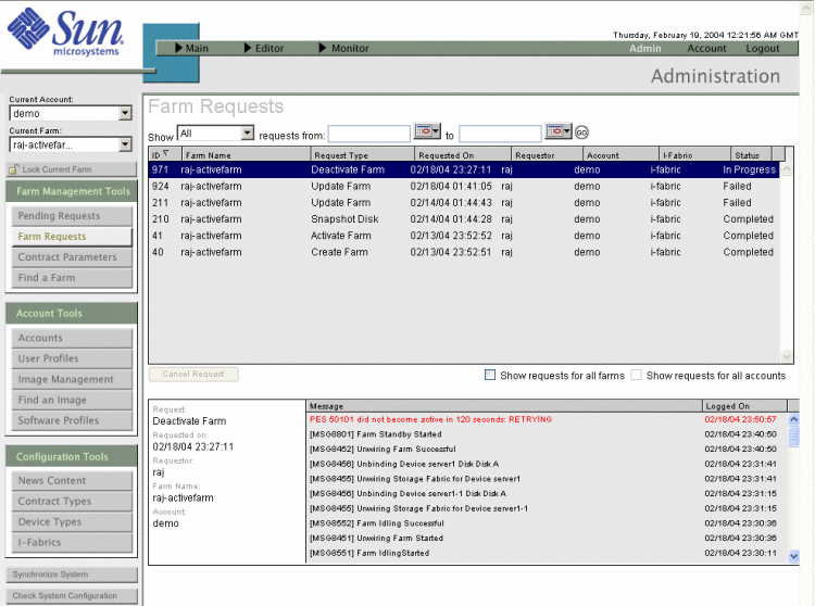
This screen contains three main sections.
Figure 2–4 Administration Screen
-
Tools bar on the left side of the screen provides direct access to all the main features of the Administration screens.
-
Navigation bar at the top of the screen provides access between User and Administration screens of the Control Center.
-
Content displays on the right of the tools bar and below the navigation bar. This area displays the contents of each screen selected from the tools bar.
Navigation Bar
The navigation bar is common to all major screens in the Control Center. Use the navigation bar to perform the following actions.
-
Toggle between the Main, Editor, Monitor, and Administration screens.
-
Toggle between farms and different screens of the Control Center.
-
Access the Support and Account sections.
-
Logout of the Control Center.
The left part of the navigation bar provides access between the Main, Editor, and Monitor screens:
-
Main – Create users and accounts and view farms in selected accounts.
-
Editor – Select a farm to view or edit from the drop-down list.
-
Monitor – Select an active farm to monitor from the drop-down list.
On the right side of the navigation bar are the following options:
-
Admin – Access to the Administration screen (only available when you are logged in with administrator access privileges)
-
Account – To manage your user accounts
-
Logout – To exit the Control Center
The active screen in the Control Center is indicated by the highlighted screen name on the navigation bar and the title displayed on the bottom right. For example, Admin is highlighted on the navigation bar and the title Administration is displayed at the bottom right corner of the navigation bar.
Tools Bar
The tools bar of the Administration screen enables you to select the current account and farm, and various administration tools to perform administrative tasks. The tools bar includes the following features:
-
Current Selections area where you can select the current account and farm with which to work
-
Lock Current Farm option to toggle the current farm between a locked and unlocked status
-
Administration Tools area to perform various administrative tasks
-
System Buttons so you can synchronize devices and software images known to the control plane software with the Control Center software
Current Selections
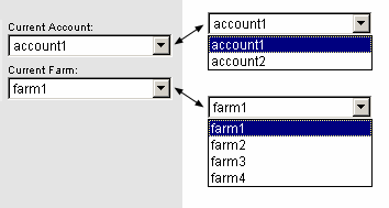
In the upper left corner of the window, you can select the account and farm associated with the account with which to work.
-
Current Account is used as the default account for all administration tasks. The selected current account gives you the ability to access all farms in the account.
-
Current Farm is the default farm displayed when navigating to other sections of the Administration screen. For example, the farm selected in the Current Farm is the default when options under the Farm Management Tools is selected.
Figure 2–5 Current Selections
Lock Current Farm
As an administrator, you can use the Lock Current Farm option to prevent others from modifying a farm as long as you have the farm locked. With this feature, you toggle the current farm between the locked and the unlocked state. When you lock (and unlock) the farm, you must enter and confirm a password that is specific to that lock. If you forget your farm lock password, you can reset the password by using the command-line interface.
This function is applied only to farms that are in the active state.
Modifying Current Farm
The Control Center is a multi-user application. Hence, any user can edit any farm, user, or account at any time if the user has permission to do so. If two users make a change to the same farm, user, or account at the same time, the changes that the first user saves are applied. The second user to save changes is given the opportunity to overwrite the change by the first user. Otherwise, the second user's changes are discarded.
Administration Tools
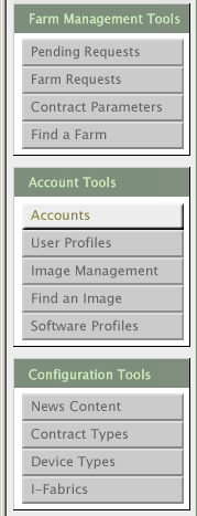
The features of the Administration section are grouped into three categories, as shown in the Administration Tools area of the Control Center window in Figure 2–6.
-
Farm Management Tools, for managing server farms.
-
Account Tools, for managing accounts.
-
Configuration Tools, for configuring basic features of the application.
Figure 2–6 Administration Tools
System Buttons
The Control Center window contains two system buttons, as described in the following list.
-
Synchronize System is used for synchronizing devices and software images that are known to the control plane with the Control Center application.
Note –Click Synchronize System whenever you add devices to an I-Fabric or when you add or change global software images using the command-line interface. Also synchronize system after you add a new I-Fabric.
-
Check System Configuration is used for validating I-Fabric configurations during the N1 Provisioning Server software installation.
Also check the system configuration each time you change a configuration parameter, such as the connector or an IP address. A dialog box displays the validation information for the system configuration and any error messages. Depending on the error that occurred, make the appropriate corrections, then check the system configuration again to ensure that the correct adjustment was made.
Editor Screen
The Editor is used by administrators and end users. You use the Editor to do the following tasks:
-
Design a new farm
-
Import a farm
-
Export a farm
-
Configure a farm
-
Activate a farm
-
Modify a farm
-
Copy a farm
-
Save a farm
-
Deactivate a farm
-
Standby a farm
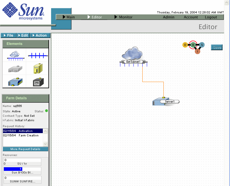
Figure 2–7 shows an example of the Editor screen.
Figure 2–7 Editor Screen
Note –
In the Editor screen, the farm view area is where you assemble, connect, and configure farm elements.
This section describes various components of the Editor and their usage:
-
Menus
-
Farm Elements Palette
-
Farm Details
-
Farm Lifecycle element
Menus
There are three menu option buttons in the Editor. The menus for a farm in Design state are File, Edit, and Submit.

Note –
This menu changes depending on the state of the farm.
Submit - Click Submit to submit a completed farm design for validation.
The following table describes the File options:
Table 2–2 File Menu Options|
Options |
Description |
|---|---|
|
Click Open to display the Open Logical Server Farm dialog box. Select a farm from a filtered list, for example, All, Design, Active, Standby, and Inactive. |
|
|
Click Save to save a new farm or save changes to an existing farm. If the farm does not have a name, you are prompted to provide one. |
|
|
Click SaveAs to save an existing farm as a new design. This is useful for using an existing farm as a template for creating new farm designs. |
|
|
Click Delete to delete a farm in Design state or Inactive state. The following message displays. You are about to permanently remove the current farm. Proceed? Click OK to proceed. |
|
|
Click Rename to change the name of current farm. Only farms in the Design state can be renamed. |
|
|
Click Summary to view a textual summary of farm elements and their configurations. |
|
|
Import |
Click to Import a farm. See How To Import a Farm. |
|
Export |
Click to Export an existing farm. See How To Export a Farm. |
The following table describes the Edit options.
Farm Elements Palette
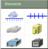
The Elements palette, available for farms in the Design and Active states, is a set of devices and networking components: External Subnet, Subnet, Load Balancer, Server, and Ethernet Port Connection.
Figure 2–8 Elements Palette
Note –
The Control Center cannot be used to configure Firewalls. This element is disabled. See Configuring Unmanaged Devices for information about using the Ethernet Port Element to represent unmanaged devices such as firewalls.
Farm Details
The Farm Details panel displays the name and location of the farm you select when you create a new design. You can view the resources that your farm consumes. Highlight an item from the Request History list to display the farm design. If you need more information regarding a farm request, you can click the More Request Details button to open the Farm Request Log screen. Figure 2–9 shows the farm details for a farm in the Active state. Also, you can view the farm that is associated with a request by selecting that request.
Figure 2–9 Farm Details
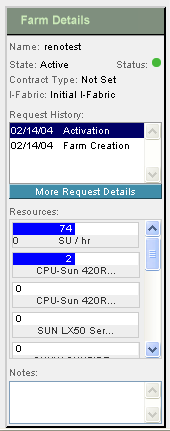
Table 2–3 describes the fields displayed on the Farm Details panel.
Table 2–3 Farm Details|
Field |
Description |
|---|---|
|
Name |
Indicates the farm name, for example, a department name such as engineering. The name is part of each device's domain name. Refer to DNS Naming Conventions. |
|
State |
Indicates the state of the farm, such as Design, Active, Standby, and Inactive. |
|
Status |
Shows the current status or health of the farm based on the monitors you have deployed. |
|
Shows the type of farm based on your terms of contract assigned by the administrator. For farms in the Design state, the value is “Not Set”. For more information on contract types, see Managing Contract Types. |
|
|
I-Fabric |
Indicates the I-Fabric where the farm is deployed. |
|
Request History |
Indicates the status of previously submitted farm update requests. Click a request to display the farm topology for that request. To view more details relating to a request, click the More Request Details button. |
|
Resources |
Displays the minimum and maximum limits for various resources in the farm and the current usage. These limits can be set and changed by the administrator for Active farms by changing the contract type. The display depends on various circumstances:
|
|
Notes |
Provides a place to record information about a farm. Notes is a good place to note changes and activity among multiple users of a particular farm or account. Note – Notes is the only editable field in the Farm Details panel. |
|
More Request Details |
Click this button to display the Account Request Log. |
Session Expiration Checking
The Editor verifies that your login session has not expired before launching any dialog boxes. Your session time-out occurs after a specified period of inactivity (for example 30 minutes) which is configured by the administrator. The default is 120 minutes. You are prompted to log in again. after you log in again, you are allowed to continue with your tasks.
Tracking Change
All changes you make in the Editor are only local in your web browser until you save the farm. When required, you can discard any changes to your farm by navigating away from the Editor, by reloading the current farm, or by loading a new farm.
If you make unsaved changes and you attempt to navigate away from the Editor, you receive a warning message that you are about to lose unsaved data.
Viewing Farm Details
You can view the request history of a farm and view the farm that was associated with each request from the Main, Editor, and Monitor screens as shown in Figure 2–10.
Figure 2–10 Farm Details Panels in Main, Editor and Monitor Screens
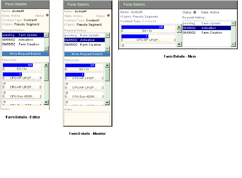
The Main, Editor, and Monitor screens enable you to see into the request queue for each farm. The Editor enables you to view the farm topology that is associated with the request.
Viewing the Account Request Log
Because users do not have access to the Farm Request option in the Administration screen, by viewing the Account Request Log users can keep track of and follow up on any of their farm update or action requests.
The Account Request Log also enables users to monitor jobs or tasks that are queued and waiting for the software automation, for example, snapshot, flex, and so on. Refer to Creating an Account Image By Using Snapshot and Adding and Removing Computing Resources from a Farm for more information on these topics.
Each request is processed in the order that the request is received. In some cases, problems in carrying out a specific task can stall the processing of subsequent requests. Users can use this feature to understand the current progress on their update request.
 How to View the Account Request Log
Steps
-
On the Main screen, click Account in the Navigation bar.
-
On the Account screen, click the Account Request Log tools bar button.
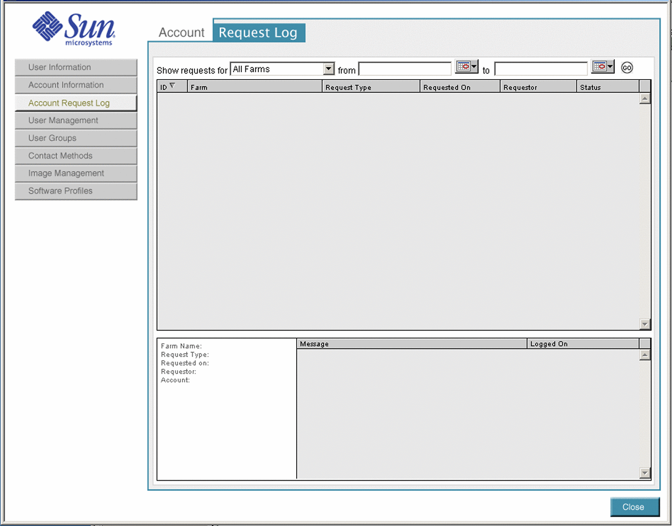
The Request Log screen appears as shown in Figure 2–11.
Figure 2–11 Account Request Log
-
Select the desired farm from the Show Request For field.
-
Select a From date and a To date to view all the requests within a date range.
-
Click Go to display the information.
Viewing Pending Farm Requests
The Pending Requests screen lists farms for which users have requested a state change. This screen displays a list of farms that are awaiting a state change. View the Pending Requests screen by clicking the Pending Requests button on the tools bar in the Administration screen of the Control Center.
You can sort pending requests in the following ways by clicking on the appropriate column heading:
-
All pending requests in all I-Fabrics
-
All pending requests in selected I-Fabric
-
Blocked pending requests in all I-Fabrics
-
Blocked pending requests in selected I-Fabric
-
In progress requests in all I-Fabrics
-
In progress requests in selected I-Fabric
The Pending Transition screen displays the listed properties.
Table 2–4 Pending Transition Screen Properties|
Property |
Description |
|---|---|
|
ID |
Farm ID |
|
Farm |
Farm name |
|
Requested Type |
The type of request. For example, a request could be to change a farm state or create an image. |
|
Requested on |
The date on which the request was made |
|
Requestor |
The user name of the requestor |
|
Account |
Account name associated with that farm |
|
I-Fabric |
The I-Fabric in which the farm resides |
|

|
Indicates a blocked request |
|

|
Indicates a high priority and is set by using the command-line interface. See Chapter 6, Troubleshooting for details. |
|

|
Indicates a critical request and is set using the command-line interface. See Chapter 6, Troubleshooting for details. |
Viewing the Farm Request Screen
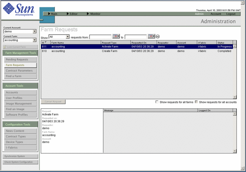
The Farm Request screen displays a history of farm requests. Access this screen by clicking the Farm Requests tools bar button from the Control Center Administration screen. You can filter the query to display farm requests in the following ways:
-
By farm or date range
-
All requests
-
In progress requests
-
Blocked requests
-
Completed requests
-
Cancelled requests
-
Queued requests
You can sort the resulting list by property by clicking the column heading. The following figure shows an example of the Farm Requests screen.
Figure 2–12 Farm Requests
Viewing Active Farms
After your farm design is activated, the state of the farm transitions to Active and the farm appears in the list of Deployed farms on the Main screen.
 How To View the Active Farm
Steps
-
Open the Main screen.
-
Click the Deployed tab in the Farm Chooser from the Control Center Main screen as shown in Figure 2–13:
Figure 2–13 Farm Chooser
-
Select the desired farm to display.
The lifecycle icon indicates the farm state.
The farm opens automatically in the Main screen. The farm is available immediately after the farm is activated.
Viewing a Farm Summary
After you create a new design and start building a farm, the Control Center provides you with a textual summary of farm elements and the farm configuration. The farm summary reflects the most recently completed change that you have made to the farm.
For farms in the Active state, the Control Center updates items such as subnet masks, IP addresses, and fully qualified domain names (FQDNs) according to the information you input when you configure the elements. You can view this textual summary of the entire configuration of a farm.
The summary screen displays the following information:
-
A high-level overview of the farm configuration
-
In-depth configuration details for each element in the farm
-
A complete listing of IP addresses and FQDNs for each subnet
Note –You can also view the configuration of individual elements in the Main, Editor, and Monitor screens by right-clicking the elements and selecting the option to view configuration. Refer to the section Viewing Element Configuration for details.
You can print a farm summary through the print function in your browser.
Summary of Farm Configuration
The summary of farm information includes:
-
Farm name
-
Farm state
-
Total number of each type of element in the farm
-
Total number of each type of device in the farm
-
User notes for the farm
-
Configuration information for each element
Element Configuration Details
The following table lists the summary of information displayed for each farm element and device:
Table 2–5 Elements Configuration Details
 How To View a Farm Summary
Steps
-
On the Admin screen, click Editor in the Navigation Bar and choose the desired farm from the Editor drop-down list.
The Editor screen appears.
-
Choose Summary from the File menu.
The Farm Summary appears.
Viewing Element Configuration
After a farm is active, the Control Center displays items such as subnet mask and IP addresses to reflect the specifics of the live farm. You can view the following details on individual element configurations:
Table 2–6 Element Configuration
You can view configuration on the Main, Editor, and Monitor screens.
 How To View Element Configuration
Steps
-
Open the active farm in the Main, Monitor, or Editor screens.
-
Right-click the element.
A pop-up menu appears
In Main and Monitor
In Editor


-
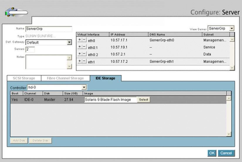
Select View Configuration (Main) or Configure (Editor) to display the following configuration screen.
Monitor Screen
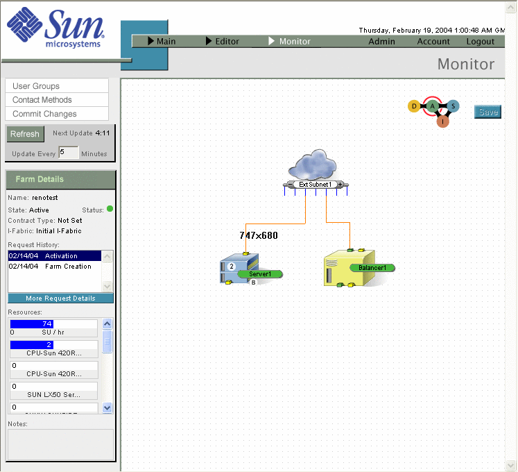
The Monitor screen is used by administrators and end users. Monitoring is the mechanism used to ensure that the elements that are associated with the farms are behaving as expected. Every element in the farm is monitored to ensure network connectivity and basic responsiveness of the device. In addition, servers contain a special monitoring agent that enables you to configure monitoring beyond that of basic network connectivity.
The monitor component gives you various options for setting up and controlling the monitoring of your farm element. Figure 2–14 shows an example of the Monitor window.
The monitoring component of the Control Center enables you to do the following tasks:
-
Configure server specific monitors
-
Configure visual and email-based alarms
-
View the time-based status of the monitors
Monitors and alarms can be edited in the Configure Monitor dialog box or the Configure Alarm dialog box. You can reach dialog boxes through the Monitor screen.
Note –
Only the latest known (stable) state of the farm is displayed in the Control Center Monitor screen.
Figure 2–14 Monitor Screen
Monitor Option Buttons
The Monitor option buttons located at the left side of the Editor area enable you to perform various operations in the Monitor. The User Groups and Contact Methods buttons are displayed only if you have account manager or administrator privileges. The Monitor buttons include the following options:
|
Option |
Description |
|---|---|
|
User Groups |
Enables you to group users for automatic notification of monitoring alarms. This button links to an option in the Accounts area and launches a separate window. |
|
Contact Methods |
Enables you to set up lists of groups and preferred methods of contact for monitoring alarm notification. This button links to an option in the Accounts area and launches in a separate window. |
|
Commit Changes |
Saves any monitor or alarm changes, causing them to be uploaded and deployed for monitoring. This action commits the changes made since the last commit and generates a farm update request. |
Clicking Commit Changes can cause a disruption in monitoring while the changes are applied, because the update can take a while to be applied. Do not click Commit Changes twice because this action sends another update. Entries made in the various monitor and alarm windows and dialog boxes are recorded as you make them, but they are not saved until you click the Commit Changes button on the Monitor screen.
Logging In to the Control Center
The first time you log in as an administrator, the default username is root with password root. You should change this information immediately after you log in the first time.
A user default account has also been created for you. The user account default username is demo with password demo.
A default security certificate is provided for the Control Center. This security certificate will expire after six months. To update this certificate or to install a new certificate see Sun ONE Application Server 7 Administrator's Guide to Security.
 How
to Log In from the Browser
Steps
-
Type the URL in the browser's address field to access the Control Center. The URL is the location where the Control Center software is installed.
http://server.domain:port
-
Click Login Page to display the Login screen.
-
Provide your username and password.
-
Click Log in to access the Control Center Administration screen.
The Administration screen appears in a new secure window.
The first time you log in, the Control Center Administration screen might be blank. On subsequent logins, the screen displays the Administration screen feature with which you previously interacted.
 Caution –
 The Control Center runs on a Microsoft® Internet Explorer 6.0 browser but does not work with the browser navigation controls. These controls are disabled intentionally. Do not navigate by using the keyboard short cuts such as Ctrl+K, F5, Alt+ Left or Right and so on, because unpredictable behavior occurs.
Chapter 3 Account Administration
This chapter describes Control Center account management concepts and procedures. This chapter shows you how to set up contract types, create users, and publish news content. Managing Control Center accounts requires administrator access privileges.
This chapter includes the following topics:
Account Concepts
A Control Center account contains a group of people, or account members, who have management access and control of a set of logical server farms within an I-Fabric.
The Control Center can contain multiple accounts, each managed by account managers. Accounts may serve multiple users that manage multiple farms across I-Fabrics.
Accounts include the following information:
-
Login information and privileges for people authorized to manage farms in the account
-
Information on the organization or department that owns the account
-
Contract data (quotas) defining farm level resource limits
-
Collection of farms for which this account has management responsibility.
Access to functions and capabilities within the Control Center is based on access privileges. You administer access privileges by defining users in the Control Center in terms of their level of authority and associated privileges. There are three classes of access privileges:
-
Administrator privileges enable management of an entire I-Fabric or multiple I-Fabrics. Users with Administrator privileges have access to all accounts in these I-Fabrics.
-
Account Manager privileges enable management of a specific account and the users within that account.
-
User privileges allow management of farms within a specific account. User privileges do not allow changes to account-wide settings or management of other users.
Administering accounts involves defining the following items:
-
Access privileges
-
Contract types to name the resource provisioning limits for the farms that are associated with an account
Do not confuse Administrator privileges for the Control Center with administrative login access to special devices in an I-Fabric. There are other types of access for the administrators to I-Fabric components, such as the control plane, resource layer, and fabric layer. Access to these components is protected by login privileges. See I-Fabric Security in N1 Provisioning Server 3.1, Blades Edition, System Administration Guide for the details of managing login access to specific control and fabric layer devices.
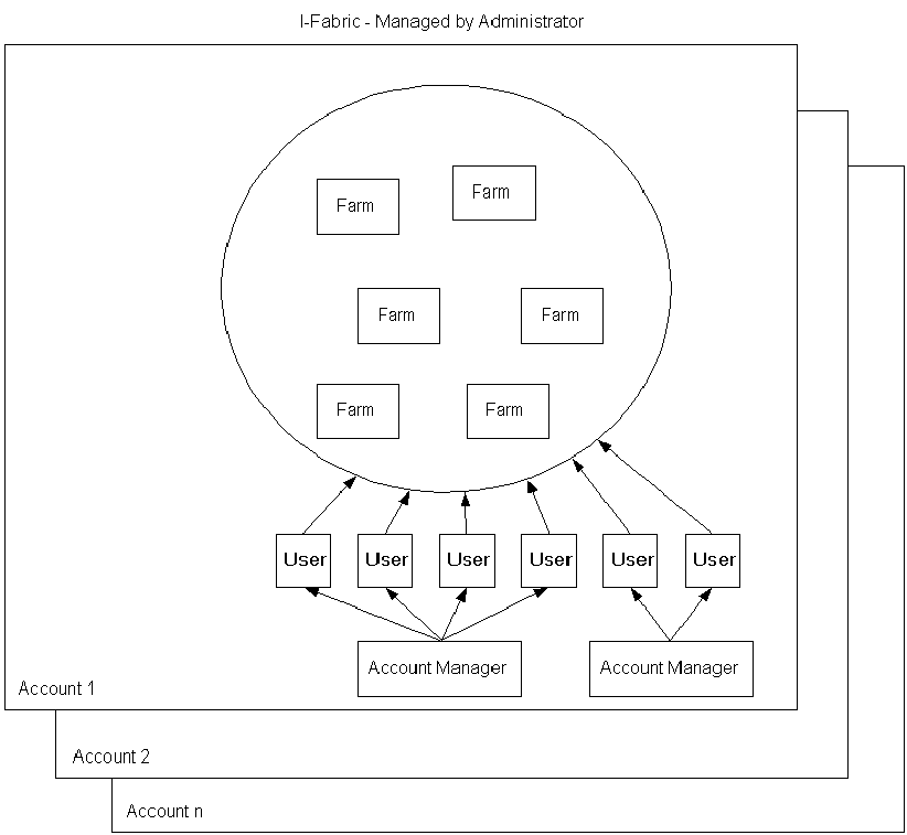
Figure 3–1 illustrates how the administrator, account, account manager, and farms relate to each other within an I-Fabric:
Figure 3–1 Account Hierarchy
Understanding User Accounts
Control Center users must have user accounts with the appropriate user roles defined for their job functions. The following table lists the Control Center user roles and the job functions and authority level:
Table 3–1 Control Center User Roles
Users and account managers have access to the following options:
Table 3–2 Account Options and User Privileges|
Option |
Permitted Tasks |
User Privilege Required |
|---|---|---|
|
User Information |
Establish your user information, such as, email and telephone numbers, and identification question and answer. You can also view your user role. |
User, Account Manager |
|
Account Information |
Maintain company account information. |
Account Manager |
|
Account Request Queue |
Display all your requests, for example, submit or deactivate or activate a farm, in the order they were requested. |
User, Account Manager |
|
User Management |
Add and delete users from your organization who can have access to the account in the Control Center. Establish user's contact information, login account, user role, and authentication information. |
Account Manager |
|
User Group |
Add and delete user groups and associate users with each group for purposes of configuring alarms. |
Account Manager |
|
Contact Methods |
For monitoring alarms, define groups of users to be contacted and method of contact. |
Account Manager |
|
Server Image Management |
Manage software images for your account. |
Account Manager and User |
DNS Naming Conventions
All farm and element names must adhere to the following DNS naming conventions. The DNS name must satisfy the following requirements:
-
Must not exceed 25 characters in length
-
Must Start with a character, end with an alphanumeric character, and have only letters, numbers, and hyphens in between
-
Must not have a hyphen followed by a number at the end
-
Must not contain a hyphen followed by the sub-string eth followed by a number, that is, should not contain -eth* where * is a number
-
Must not match the names of other elements in a farm
-
Must not include non-English characters
Farm Naming Conventions in the Control Center
The Control Center allocates the DNS name to a farm, which is installation specific. The name is based on the following criteria:
-
The name of the farm you assigned (farmname)
-
Your account name (accountname)
-
The location of the farm in an I-Fabric (ifabricname), for example:
farmname.accountname.ifabricname.yourorgname.com
Managing Accounts
Use the Administration screen to manage accounts. Refer to Administration Screen for information on navigating the Control Center Administration screen.
This section describes how you can create, remove, or update an account. You might update an account to change the name of the organization and contact details.
Adding, Deleting, and Updating Accounts
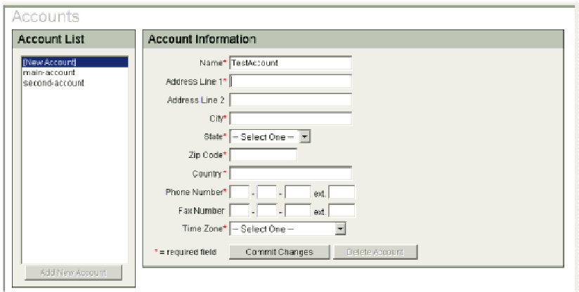
You must create an account before you can perform any other account related actions. Figure 3–2 shows the Add Accounts screen.
Figure 3–2 Add Account Screen
 How To Add
a New Account
Steps
-
Login to the Administration screen of the Control Center.
The Account Tools buttons are appear in the left pane.
-
Click Accounts on the tools bar.
The Accounts dialog box appears.
-
Click the Add New Account button.
-
Type the appropriate information in the Account Information dialog box fields.
Fields marked with an asterisk are mandatory fields.
Note –If the account name you have chosen already exists, an error message appears. Use a different account name. Account names are used in the Domain Name Service (DNS) names of farm elements. See DNS Naming Conventions.
-
Click the Commit Changes button.
The new account information is saved.
 How To Delete
an Account
Steps
-
Login to the Administration screen of the Control Center.
The Account Tools buttons are appear in the left pane.
-
Click Accounts on the tools bar.
The Accounts dialog box appears.
-
Select the account you want to delete from the Account List.
The account information appears in the right pane.
-
Click the Delete Account button in the right pane.
Note –You cannot delete an account if any user and farm is associated with the account. The users must be deleted first. See How To Delete a User Profile.
-
Click the Commit Changes button.
The account information is deleted.
 How To Update
an Existing Account
Steps
-
Login to the Administration screen of the Control Center.
The Account Tools buttons are appear in the left pane.
-
Click Accounts on the tools bar.
The Accounts dialog box appears.
-
Select the account you want to delete from the Account List.
The account information appears in the right pane.
-
Type updated account information into the appropriate fields.
Note –You cannot change an account name after the account is created.
-
Click the Commit Changes button.
The updated account information is saved.
Viewing and Updating Account Information
To modify account information, you must have at least Account Manager access privileges.
 How To Access the Account Information
Steps
-
From the Main screen, click Account in the Navigation Bar
-
On the Account screen, click Account Information.
The Account Information screen appears.
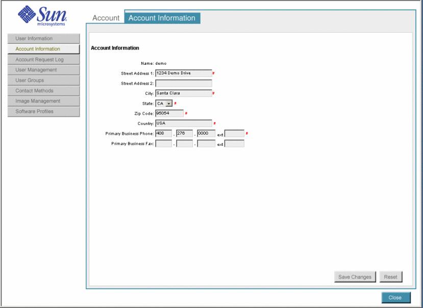
Figure 3–3 Account Information Screen
-
Type new or updated account information into the appropriate fields.
The following table describes all the fields on the Account Information screen.
Field Name
Required/Optional/Display
Description
Name
Display
Display only. Shows the account name.
Street Address 1
Optional
Type the company street address—a maximum of 200 characters.
Street Address 2
Optional
Type a second street address, such as, a department for a large company or an alternative address, such as a post office box—maximum of 200 characters.
City
Optional
Type city name—a maximum of 30 characters.
State
Optional
Select a state from the drop-down list.
Zip Code
Optional
Type a zip code.
Country
Optional
Type the country name.
Primary Business Phone
Optional
Type a valid US telephone number as the company's business phone.
Note –The extension is optional.
Primary Business Fax
Optional
Type a valid US telephone number as the company's business fax.
Note –The fax and extension is optional.
-
Click the Save Changes button.
The new account information is saved.
Adding, Viewing, and Removing Users
Account managers and administrators can set up additional users. From the User Management screen you can perform the following tasks:
-
Add new users
-
View information for an existing user
-
Remove a user
 How To Add New Users
Steps
-
On the Main screen, click Account in the navigation bar.
The Account screen appears.
-
From the Account screen, click User Management on the tools bar.
The User Management screen appears.
-
To add a user, click the Add button near the left side of the User Management screen.
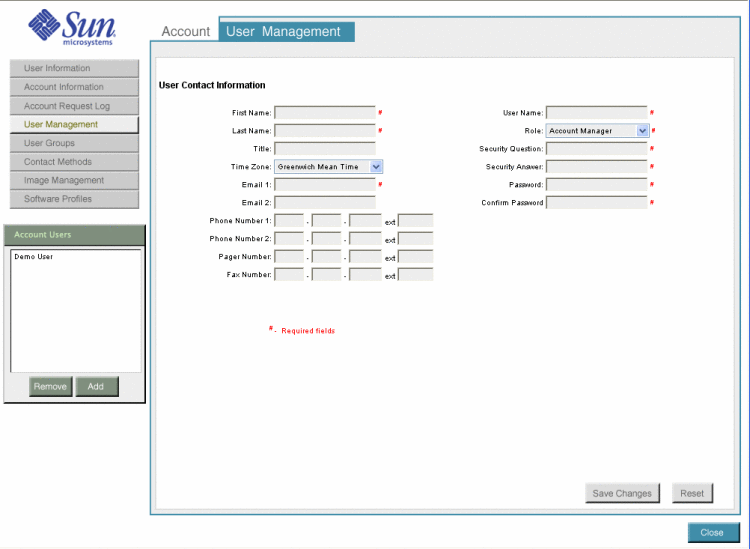
The Add User Contact Information screen appears.
Figure 3–4 User Management - Add User Contact Information Screen
-
Provide data to create a user account as described in Step 3.
-
Set up user accounts as required.
-
Click Save Changes.
-
Click the Close button to exit the screen.
 How To View Information for an Existing
User
Steps
-
On the Main screen, click Account in the navigation bar.
The Account screen appears.
-
From the Account screen, click User Management in the tools bar.
The User Management screen appears.
-
Select the user from the Account Users list in the left pane.
The user information appears in the right pane.
-
Click the Close button to exit the screen.
 How To Remove a User
Steps
-
On the Main screen, click Account in the navigation bar.
The Accounts screen appears.
-
From the Account screen, click User Management in the tools bar.
The User Management screen appears.
-
Select the user from the Account Users list in the left pane.
The user information appears in the right pane.
-
Click the Remove button.
-
Confirm your choice.
-
Click Close to exit the screen.
Adding User Groups
User groups provide a pool of people to contact for farm problems. The monitoring system can use this information for automatic notification when an alarm occurs. In addition, administrators use this information if they need to contact people as necessary. You cannot place a group within a group. You are required to have account manager or administrator access privileges to set up user groups.
You can do the following tasks:
-
View user group details
-
Create a new user group
-
Add users to or remove users from an existing user group
-
Remove user group
 How To Add a User Group
Steps
-
On the Main screen, click Account in the navigation bar.
The Account screen appears.
-
From the Account screen, click User Groups in the tools bar.
The User Groups screen appears.
-
To add a new user group, click the Add button .
The Add New User Group screen appears.
-
Type a new user group name in the Name field.
-
To add users to the new user group from the existing user list, select the user name and click the Add button.
-
Click the Save Changes button.
The new user group is saved.
-
Click the Close button to exit the Add User Groups screen.
Changing User Information
When users receive their login name and password for the Control Center, only the user or the administrator can modify this contact information. Administrators or the user can change this password and set up the contact information that is used for monitoring alarms.
Across various Control Center account functions, the following conditions apply:
-
Required fields are marked with a red pound sign (#)
-
Text in red indicates that required information is missing
 How To Change User
Information
Steps
-
On the Main screen, click Account on the navigation bar.
The Accounts screen appears.
-
From the Account screen, click User Information in the tools bar.
The User Information screen appears with user information highlighted with a red pound sign.
-
Provide user information using the guidelines in the following table.
-
Click the Save Changes button.
The updated user information is saved.
Note –You can also click Reset to reset the screen to previously saved values.
 How to Change
Your User Password
Steps
-
On the Main screen, click Account on the navigation bar.
The Accounts screen appears.
-
From the Account screen, click User Information in the tools bar.
The User Information screen appears.
-
Type the existing user password into the Password field.
The password must be less than 15 characters in length.
-
Type the new password into the New Password field.
The password must be less than 15 characters in length.
-
Retype the new password into the Re-enter New Password field.
-
Click the Save Changes button.
The new user password is saved.
Setting Up Contact Methods
A contact method defines a group or list of groups and a preferred method of contact for each group in case of a monitoring alarm. You need to have Account manager or administrator access privileges to set up Contact Methods.
You can do the following tasks:
-
View Contact Methods details
-
Create new Contact Method
-
Add or remove user groups to or from an existing Contact Method list
-
Remove Contact Method
 How To Add Contact Methods
Steps
-
On the Main screen, click Account on the navigation bar.
The Account screen appears.
-
Click Contact Methods in the tools bar.
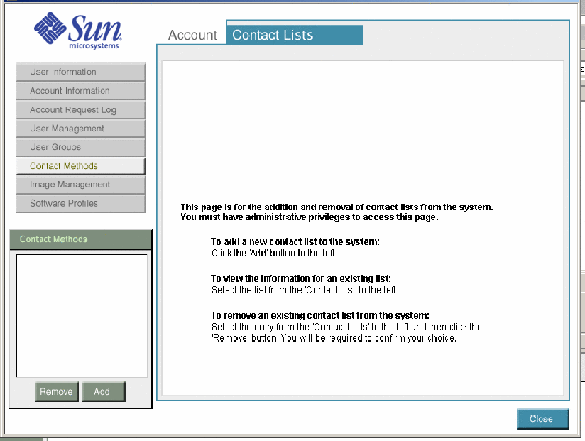
The Contact Lists screen appears.
Figure 3–5 Contact Lists Screen
-
Click the Add button.
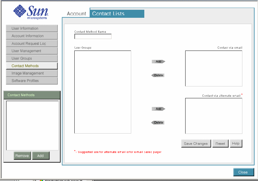
The Account Contact Lists screen appears. This screen identifies users in each group to be contacted by the regular email address or by the alternate email address.
Figure 3–6 Contact Method - Add
-
Type a contact method name.
-
Select user groups from the existing user group list and click the Add button to add the user group to the appropriate contact option.
-
Use Contact via Email to contact users through a primary email account.
-
Use Contact via Alternate Email to contact users through a secondary email account such as a pager.
-
-
Click the Save changes button.
The new contact methods are saved.
-
Click the Close button.
The Account Contact Lists screen is closed.
Managing User Profiles
The User Profiles screen allows administrators to add, update, and delete administrators, account managers, and users. In addition, you can view a user's login status. Users and account managers are associated with the currently selected account from the current account drop-down list.
Administrators are not associated with any account.
In the User Profile section you can add, delete, or update user information.
Adding, Deleting, and Updating User Profiles
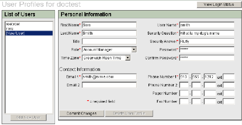
The User Profiles window has three sections of user information:
-
List of Users
-
Personal Information
-
Contact Information
Figure 3–7 illustrates the screen to add a new user:
Figure 3–7 User Profiles
 How
To Add a New User Profile
Steps
-
Log in to the Control Center Administration screen.
-
Click the User Profiles button in the tools bar.
-
Click the Add New User button and fill in all the required fields marked with an asterisk.
-
Select the user role from the Role drop-down list in the Personal Information area.
Select Administrator, Account Manager, or User.
The format for the phone and fax field is ###-###-####.
-
Click the Commit Changes button.
The new user profile is saved.
 How To Delete a User Profile
Steps
-
Log in to the Control Center Administration screen.
-
Click the User Profiles button in the tools bar.
-
Select the user account from the Current Account drop—down list above the tools bar.
-
Select a user name in the List of Users area.
All pertinent information about the user is displayed automatically in the dialog box after you select the user to be removed.
-
Click Delete User Profile and then click OK in the confirmation window.
The user profile is removed.
 How
To Update a User Profile Information
Steps
-
Log in to the Control Center Administration screen.
-
Click the User Profiles button in the tools bar.
-
Select the user profile from the List of Users in the User Profiles screen.
All pertinent information about the user displays automatically in the dialog box after you select the user to be updated.
-
Provide the update information in the appropriate fields.
Fields marked with an asterisk require information.
The format for the phone and fax field is ###-###-####.
-
Click Commit Changes.
User Login Status
The Login Status dialog box enables you to view users login status and manually lock and unlock users. By default, users are locked out of the system if their login attempts fail a configurable number of times within a configurable number of minutes. The lock is automatically released after another configurable number of minutes.
 How To View and Change the Login Status
of Account Users
Steps
-
Log in to the Control Center Administration screen.
-
Click the User Profiles button in the tools bar.
-
Click the View Login Status button on the top right corner of the User Profile screen.
-
Select the account from the User Login Status For drop-down list to view the login status of the user profiles associated with the account.
-
To change the login status of a user, use the Locked check box in the far right column.
-
To unlock a user, deselecting the Locked check box and clicking Commit Changes.
-
To lock out a user, select the Locked check box next to the user's name and click Commit Changes.
Note –Manually set locks do not expire so, you need to manually unlock the Locked check box to enable the user access to the Control Center.
-
Managing Contract Types
Contract types define a profile, or template, of resource provisioning permissions that can be used to restrict the allowable changes that you can make to a farm or farms. For example, an administrator can create a contract type that only allows the addition and removal of servers and restricts a farm from all other changes. Consequently, any farms linked to that contract type are limited to changes only in number of servers.
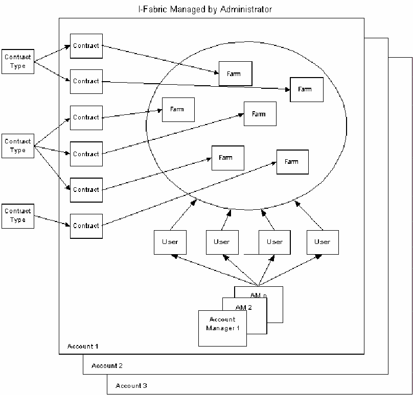
Contract types are global and do not belong to any particular account. Contract Types provide the template from which specific contracts are derived for each server farm. Contract Types define the resource provisioning permissions on which the farm contracts are based. The following figure illustrates how the contract types, contracts, administrators, account, account manager, and farms relate to each other within an I-Fabric.
Figure 3–8 Contract Hierarchy
Contract types enable you to set resource provisioning in the following ways:
-
The minimum and maximum limits (add, change, and remove) for various resources in the farm. You can set and change these limits for active farms by changing the contract type.
-
The term flexing describes the capability to add or remove computing resources in a farm. Flexing can refer to the ability to add an additional server to a server group. Flexing can also refer to the ability to add, remove, rearchitect, or reconfigure a farm.
-
A way to abstract any individual device to enable a utility like computing service. If you want to implement service units as a strategy to manage I-Fabric resources, contact your Sun Service Provider for more information.
 How
To Add a Contract Type
Note –
Contract type names are case sensitive.
Steps
-
On the Main screen, click Admin on the navigation bar.
-
Click the Contract Types button in the Configuration tools bar.
-
Click Add Contract Type.
-
In the Name field, type the name of the contract.
The length cannot exceed 30 characters.
Note –If another contract with the same name already exists within the system, an error message displays, and you are prompted to rename the contract.
-
In the Description field, type a brief description, up to 255 characters in length, for the type of contract.
-
Select a minimum system from the Minimum System drop-down menu. The available choices are No Minimum, SUs Only, Hardware Types only, or SUs and Hardware Types.
-
If either the minimum or maximum parameter of the selected farm type is of SUs only or SUs and Hardware Types, you must enter a value between 0 and 2147483647 for the SU fields, except when No Maximum is selected.
-
Select a maximum system from the Maximum System drop-down menu. The available choices are No Maximum, SUs Only, Device Types only, or SUs and Hardware Types.
Note –SUs defined during I-Fabric Implementation only denotes that the limit is based on total service units, while Device Types denotes that the limit is based on the types and quantities of devices.
-
In the Flex Permissions for Active Farms window, select or deselect each resource type to grant or deny permissions for performing various actions on a resource type.
-
Select Create to give users permission to add the resource to an active farm.
-
Select Remove to give users permission to remove a resource from an active farm.
Note –The flex permissions only apply to the Control Center User and Account Manager profiles. As an administrator, you are not bound by this restriction when working in the Editor. You can flex up or flex down a farm and commit your changes. However, this request for flex creates a BLOCKED_REQUEST in the I-Fabric to indicate that the flex request has been blocked. You can check whether the resources exist in the I—Fabric and unblock the request to allow flexing to become effective. Refer to How To Unblock a Farm Activation Request for information on how to unblock farm requests.
-
-
Click Commit Changes to initiate the creation of the contract type.
See Also
 How To Delete a Contract Type
Before You Begin
You cannot delete a contract type that is in use.
Steps
-
On the Main screen, click Admin on the navigation bar.
-
Click the Contract Types button in the Configuration tools bar.
-
Select the contract type from the Contract Type List.
-
Click the Delete Contract Type button.
-
Click OK in the confirmation dialog box.
 How To Update Contract Type
Before You Begin
You can update a contract type to include or exclude flex permissions or change the minimum and maximum system allowed in the farm.
Steps
-
On the Main screen, click Admin on the navigation bar.
-
Click the Contract Types button in the Configuration tools bar.
-
Select the contract type from the Contract Type List.
-
In the Description field, type a brief description, up to 255 characters in length, for the type of contract.
-
Change the Minimum System and the Maximum System values, if required.
-
Change the Flex Permissions for Active Farms, if required.
-
Click Commit Changes when you finish updating the contract type.
Setting Contract Parameters
You set contract parameters to provide specific resource provisioning permissions for each farm. When you set contract parameters, you can accept the default resource provisioning that is defined by the contract type you select. You can also choose to adjust the resource provisioning permissions on a farm-by-farm basis. The Contract Parameters dialog box enables you to associate farms with predefined contract types as described in Chapter 3, Account Administration.
 How To Set Contract Parameters
Steps
-
On the Main screen, click Admin on the navigation bar.
The Control Center Administration screen appears.
-
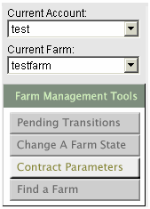
Select the appropriate account and farm at the left-hand side of the screen.
-
Click Contract Parameters in the Farm Management tools bar.
-
Select the contract type from the Farm Contract Type drop-down list that displays all the contract types currently defined in the system.
Depending on the Minimum and Maximum parameters of the selected contract type, you can specify minimum and maximum values for service units, all hardware in the I-Fabric, or both. If either the minimum or maximum system parameter of the selected farm type is of Service Units (SU) only, or SUs and Hardware Types, you must enter a value between 0 and 2147483647 for the Service Units field(s), except when unlimited maximum is selected.
Service Units is defined as a way to abstract any individual device to enable utility-like computing service. If you are interested in using SUs as a method for providing flexible pay-for-use computing resources to your users, contact Technical Support for information on the SU-based service model.
The optional Start Date and End Date determine the effective period of the farm contract type. The Start Date field defaults to the Start Date entered during farm submission. Submit saves the changes, and Reset reloads the farm's last saved contract type.
-
Click Submit.
Managing News Content
This section describes how to create news content for the Main screen of the Control Center. You can publish a news item to either all accounts or a specific account. You can choose whatever news item you deem pertinent to the user.
The News Content screen contains the following sections:
-
Category
-
Story Preview
-
Story Editor
In the categories section, top left, you can add, remove, or update a news category. When you click Add Story, a dialog appears asking for the new category's name and a brief description. When you click Remove Story on a highlighted category, the highlighted category is removed from the category list. Click the Update Story button to update the description and name of an existing (highlighted) category in the list.
You can control the order in which the categories are displayed on the user Main screen in the Control Center by selecting a category and clicking the up or down arrow next to the list of categories. The order in which you select the categories is the same order in which the users will see them on the Main screen. When users first access the screen, the top-most category is selected by default.
The Story Preview window enables you to preview an article that you have selected from the Articles drop-down list in the Story Editor window.
The Articles drop-down list lets you preview, remove, or update existing articles, and create new articles. To preview an existing article, select an article from the drop-down list. To remove or update that article, click the Remove Story or Update Story button at the top right of the article management window.
Note –
You will receive an error if you copy and paste characters outside the supported Latin-1 character set (ISO-8859-1) into a news message.
 How
To Add and Publish An Article
Steps
-
From the Account drop-down menu, select the account to which you want to publish the article.
If you want to publish the article to all accounts, select All Accounts.
Note –Carefully consider the content of the article before publishing the article to all accounts.
-
In the Link Title field, enter the title for links to the article.
-
Enter the Article Title in the next field.
-
Enter the Byline in the next field.
-
Choose the date, time, and time zone you want from the drop-down lists.
Pacific Standard Time is the default time zone.
-
Enter the content of the article in the content window. HTML tags entered in this window are properly interpreted.
 Caution –
 Use extreme caution, as careless usage of HTML tags can interfere with the appearance and function of the Control Center user interface.
-
Click Preview Story to preview the article as the article will appear on the Main screen (user screen) of the Control Center and edit as necessary.
-
When you are ready to publish the article, click Commit.
- © 2010, Oracle Corporation and/or its affiliates
