| Skip Navigation Links | |
| Exit Print View | |

|
Sun Server X4-2L HTML Documentation Collection |
Getting the Latest Software and Firmware
About the Installation Procedure
Installation Procedure Overview
Preparing for Server Installation
Server Physical Specifications
Tools and Equipment Needed for Installation
Optional Component Installation
About Server Features and Components
Front Panel Status Indicators, Connectors, and Drives
Back Panel Status Indicators, Connectors, Drives, and PCIe Slots
Server Management Software Overview
Getting Server Firmware and Software Updates
Firmware and Software Access Options
Getting Firmware and Software From MOS or PMR
Installing Updates Using Other Methods
Installing the Server Into a Rack
Safety Precautions When Rackmounting the Server
Stabilize the Rack for Installation
Attach Tool-less Slide-Rail Assemblies
Install the Server Into the Slide-Rail Assemblies
Install the Second-Generation Cable Management Arm
Remove the Second-Generation Cable Management Arm
Install the First-Generation Cable Management Arm
Verify Operation of Slide-Rails and CMA
Rear Cable Connections and Ports
Attaching Data Cables to the Server
Connecting Power Cords to the Server
Oracle ILOM Hardware and Interfaces
Logging In to Oracle ILOM Using a Local Serial Connection
Logging In to Oracle ILOM Using a Remote Ethernet Connection
Accessing the Host Console Through Oracle ILOM
Troubleshooting the Service Processor Connection
Setting Up Software and Firmware Using Oracle System Assistant
Accessing Oracle System Assistant
Setting Up Software and Firmware Using Oracle System Assistant
Set Up Software and Firmware Using Oracle System Assistant
Setting Up an Operating System and Drivers
Configuring Server Drives for OS Installation
RAID Configuration Requirements
Configuring Storage Drives Into RAID Volumes Using Oracle System Assistant
Configuring RAID Using the BIOS RAID Configuration Utilities
Configuring the Preinstalled Oracle Solaris 11.1 Operating System
Preinstalled Oracle Solaris 11.1 Image BIOS Boot Mode Restriction
Preinstalled Operating System RAID Limitations
Oracle Solaris 11.1 Configuration Worksheet
Configure the Preinstalled Oracle Solaris 11.1 Operating System
Oracle Solaris 11.1 Operating System Documentation
Configuring the Preinstalled Oracle Linux 6. x Operating System
Preinstalled Oracle Linux Image BIOS Boot Mode Restriction
Oracle Linux 6.x Configuration Worksheet
Configure the Preinstalled Oracle Linux 6.x Operating System
Registering Oracle Linux and Activating Automatic Update
Oracle Linux 6.x Operating System Documentation
Configuring the Preinstalled Oracle VM 3.2 Software
Preinstalled Oracle VM Image BIOS Boot Mode Restriction
Preinstalled Oracle VM Server and Oracle VM Manager Compatibility Requirements
Oracle VM Server Configuration Worksheet
Configure the Preinstalled Oracle VM Server
Powering Off the Server for Orderly Shutdown
Powering Off the Server for Immediate Shutdown
Troubleshooting Installation Issues
Technical Support Information Worksheet
Locating the System Serial Number
About Oracle Solaris Operating System Installs
Oracle Solaris OS Installation Task Map
Selecting the Console Display Option
Selecting the Boot Media Option
Selecting the Installation Target Option
Oracle Solaris OS Installation Options
Oracle System Assistant Overview
Preparing to Install the Operating System
Installing the Oracle Solaris Operating System
Installing Oracle Solaris on a Single System Using Oracle System Assistant
Installing the Oracle Solaris 10 or 11 Operating System on a Single System Using Media
Oracle VM Installation Task Map
Selecting the Console Display Option
Selecting the Boot Media Option
Selecting the Installation Target Option
Oracle VM Installation Options
Oracle System Assistant Overview
Preparing to Install Oracle VM
Verify the BIOS Factory Defaults
Disable VT-d and SR-IOV in BIOS
Installing Oracle VM on a Single System Using Oracle System Assistant
Installing Oracle VM on a Single System Using Media
Post Installation Tasks for Oracle VM
Configuring Network Interfaces
About Linux Operating System Installs
Supported Linux Operating Systems
Oracle Unbreakable Enterprise Kernel for Linux
Selecting the Console Display Option
Selecting the Boot Media Option
Selecting the Installation Target Option
Oracle System Assistant Overview
Preparing to Install the Operating System
Installing a Linux Operating System
Installing a Linux OS on a Single System Using Oracle System Assistant
Installing Oracle Linux on a Single System Using Media
Installing Red Hat Enterprise Linux on a Single System Using Media
Installing SUSE Linux Enterprise Server on a Single System Using Media
Configuring Network Interfaces
About Microsoft Windows Server Operating System Installs
Windows OS Installation Task Map
Supported Windows Operating Systems
SAS PCIe HBAs Requiring LSI Mass Storage Driver for Windows Server 2008 SP2
Selecting the Console Display Option
Selecting the Boot Media Option
Selecting the Installation Target Option
Windows OS Installation Options
Oracle System Assistant Overview
Preparing to Install the Operating System
Installing a Windows Server Operating System
Installing Windows Server on a Single System Using Oracle System Assistant
Installing Windows Server on a Single System Using Media
Post Installation Tasks for Windows Server
Supplemental Software Component Options
Installing Device Drivers and Supplemental Software
VMware ESXi Installation Task Map
Supported VMware ESXi Software
Selecting the Console Display Option
Selecting the Boot Media Option
Selecting the Installation Target Option
VMware ESXi Installation Options
Preparing to Install VMware ESXi
Configuring the VMware ESXi 5.0 Software or the Server Hardware to Support Network Connections
Installing VMware ESXi on a Single System Using Media
Post Installation Tasks for VMware ESXi
Configure Network Adapter Settings
Determine the MAC Address of a Connected Server Network Port
Update the VMware ESXi Software
Configuring Network Interfaces
About Server and Component Status Indicators
Service Troubleshooting Task List
Locate the Server Serial Number
Electrostatic Discharge Safety
Preparing the Server for Component Replacement
Servicing CRUs That Do Not Require Server Power-Off
Servicing Storage Drives and Rear Drives (CRU)
Servicing Power Supplies (CRU)
Servicing CRUs That Require Server Power-Off
Servicing the SAS Expander Module (CRU)
Servicing the Air Baffle (CRU)
Servicing the Internal USB Flash Drives (CRU)
Servicing the Front and Rear Storage Drive Backplanes (FRU)
Servicing the Front LED/USB Indicator Modules (FRU)
Servicing the Motherboard Assembly (FRU)
Returning the Server to Operation
Server Filler Panel Requirements
Remove and Install Filler Panels
Reinstall the Server Chassis in the Rack
Return the Server to the Normal Rack Position
Reconnect Power and Data Cables
Setting Up BIOS Configuration Parameters
Managing the BIOS Configuration
Accessing the BIOS Setup Utility
Access BIOS Setup Utility Menus
Navigate BIOS Setup Utility Menus
Selecting Legacy BIOS or UEFI Boot Mode
Switching Between Legacy BIOS and UEFI BIOS
UEFI BIOS Boot Mode Advantages
Configuration Utilities for Add-In Cards
Using BIOS for Resource Allocation
Common BIOS Setup Utility Tasks
Verify BIOS Factory Default Settings
Select Legacy BIOS or UEFI BIOS Boot Mode
Enable or Disable Oracle System Assistant
Configure I/O Resource Allocation
BIOS Setup Utility Menu Options
UEFI Driver Control Menu Selections
BIOS Save & Exit Menu Selections
Monitoring Components and Identifying SNMP Messages
Monitoring Component Health and Faults Using Oracle ILOM
Before You Begin
iSCSI virtual drives are used primarily to run supported operating systems that reside on an external server that function as the Sun Server X4-2L host operating system.
iSCSI virtual drives must be configured in the iSCSI BIOS Setup Utility screens. You must set the iSCSI parameters on the selected port.
Before you begin:
You should be familiar with iSCSI theory of operation for the selected OS.
Refer to the OS documentation to verify that ISCSI targets can be mounted on a client.
You will need access to an external iSCSI server running on any supported OS.
The Sun Server X4-2L must be in UEFI BIOS Boot Mode, not Legacy BIOS Boot Mode.
You must provide the following information from the iSCSI target server. The following items are entered into the iSCSI BIOS Setup Utility screens:
| ||||||||||||||||||||||||
Options displayed include iSCSI booting and all controllable devices.
Note - The selection for iSCSI will always be an option in UEFI BIOS Boot Mode; however, other menu options might change depending on which cards are installed in the system.
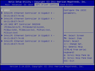
The iSCSI Initiator Name screen appears.
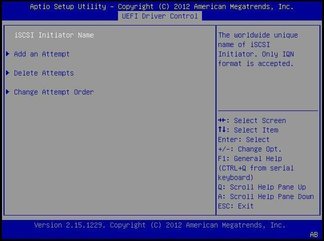
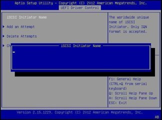
The iSCSI Initiator Name dialog box appears.
The IQN identifies:
The string “iqn”
A date code that specifies the year and month in which the organization registered the domain or subdomain name used as the naming authority string
The organizational naming authority string, which consists of a valid, reversed domain or subdomain name
Optionally, a “:” (colon) followed by a string that the assigning organization can choose, which must make each assigned iSCSI name unique
The iSCSI Initiator Name must conform to the IQN naming scheme (see RFC 3271 – Internet Small Computer Systems Interface (iSCSI) Naming and Discovery). For example: iqn.1988-2.com.oracle:000000000000
The iSCSI Initiator Name appears in the UEFI Driver Control screen.
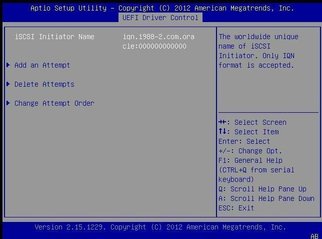
The Add and Attempt screen appears.
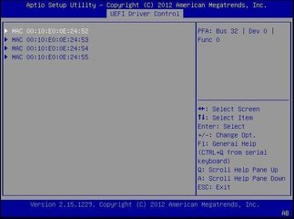
For example: Port 00-21-28-E7-71-06.
The Port Configuration screen appears. iSCSI is disabled by default.
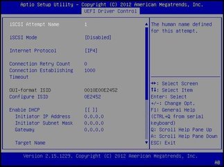
DHCP is disabled by default.
For example: iqn.1988-12.oracle.com:X4-2-target
For example: 111.111.1.11
For example: 3260 (default target port setting)
Note - When iSCSI is enabled on a network port, PXE is disabled for the port.
For example: 0
You do not need to enter the settings for the iSCSI Initiator and the related fields are hidden.
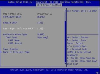
The Target information is retrieved from the DHCP service and the related fields are hidden.
The following screen shows DHCP and Get target info via DHCP set to Enabled.
None – If None is selected, the default setting, CHAP is disabled and not required.
One Way (also known as unidirectional) or Mutual – If One Way is selected, the CHAP Name and CHAP Secret are required.
CHAP Name – User configurable. Typically the name of the Initiator, but can be any name. Must also be set at the target to authenticate the Initiator.
CHAP Secret – User configurable password. Must be set on the target and the Initiator.
Mutual – If Mutual (also known as bidirectional) is selected, CHAP Name, CHAP Secret, Reverse CHAP Name, and Reverse CHAP Secret are required.
Reverse CHAP Name – Set a CHAP name for the target as a parameter of the target.
Reverse CHAP Secret – Set a password for the target.
Note - The target must be configured to acknowledge a CHAP and for the parameters to be used.
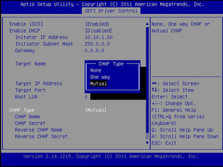
The Please Select Boot device dialog box appears.