Chassis Overview
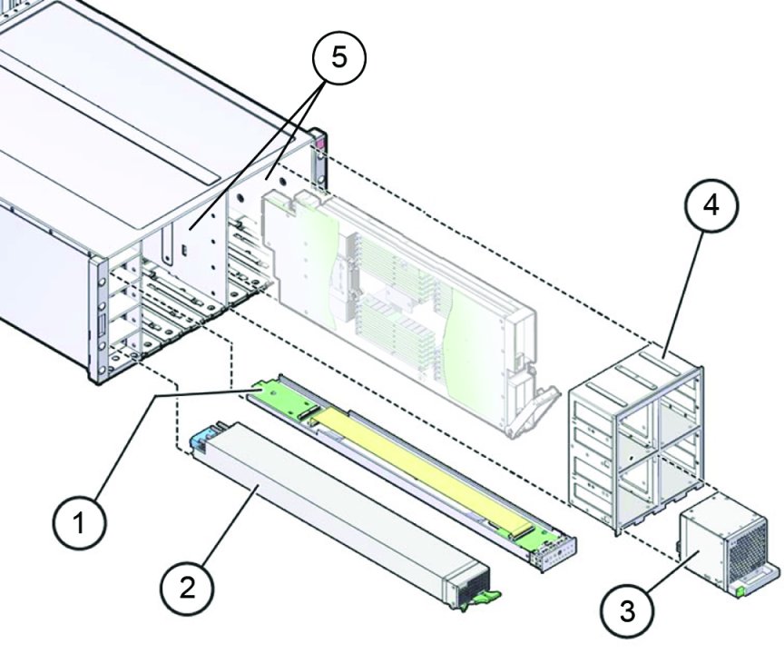
The chassis consists of the front accessible components, internal components, and components accessible from the back of the server:
Chassis Front Components
At the front of the server, the chassis includes:
-
Four power supplies
For more information about the power subsystem, see Power Subsystem.
-
Front Indicator Module (FIM)
For more information about the server management subsystem, see System Management Subsystem.
-
Eight fan modules (FMs) and two fan frames
For more information about the FMs and the chassis cooling subsystem, see Chassis Cooling Subsystem.
-
Two CPU module (CMOD) bays
CMODs are accessible from the front of the server, after removing the FMs and the fan frames. For more information, see CPU Module (CMOD) Overview.

|
Chassis Internal Components
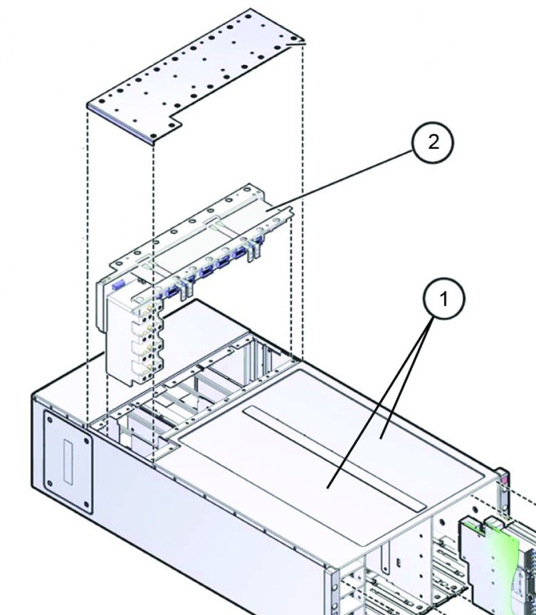
Internal components include:
-
Two CMOD bays that house four CMODs each. Removal and installation of the CMODs requires warm or cold service. For information about the CMODs, see CPU Module (CMOD) Overview.
-
The mid-plane assembly, which provides an interconnect between the rear components and the front-side components. Removal and installation of the mid-plane assembly requires cold service.

|
Chassis Rear Components
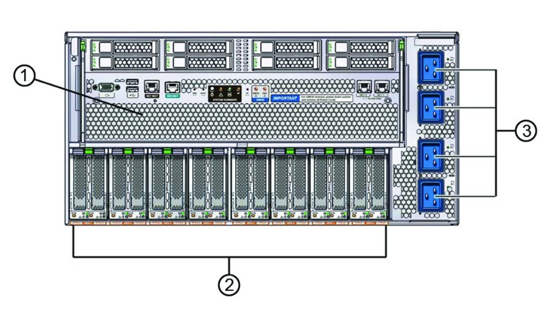
The rear of the chassis contains:
-
System Module (SMOD)
The SMOD is removable and has internal components that are not directly accessible from the rear of the server. For more information, see System Module (SMOD).
-
Dual PCIe card carrier (DPCC) bay
The DPCC bay contains eight DPCCs and up to 16 PCIe cards. For more information, see Storage and IO Subsystem.
-
AC power block
The AC power block has four AC power inlet connectors. The power block is not a removable component. For more information, see Power Subsystem.

|