CPU Module (CMOD) Overview
CPU modules (CMODs) contain the processors (CPUs) and the system memory, and supply power to the fan modules and the DPCCs.
CMODs are internal warm or cold-service components. To access the CMODs, you must remove the fan modules and the fan frames.
The following sections describe the CMOD configuration options and the internal layout of components:
Processor and Memory Overview
Each CMOD contains one Intel Xeon E7-8895 v2 15-Core, 2.8 GHz processor.
The server CMODs contain the system memory. The maximum system memory depends on the number of CMODs in the server. For a four-CMOD system, the maximum memory (DDR-1333 32 GB DIMMs) is 3 TB, and for an eight CMOD system, the maximum memory (DDR-1333 32 GB DIMMs) is 6 TB.
CMOD Configuration Options
The server supports two CMOD configurations, a four-CMOD and eight-CMOD configuration. In the four-CMOD configuration, the first four slots on the left (slots 0-3) are occupied and the four slots on the right (4-7) are unoccupied.
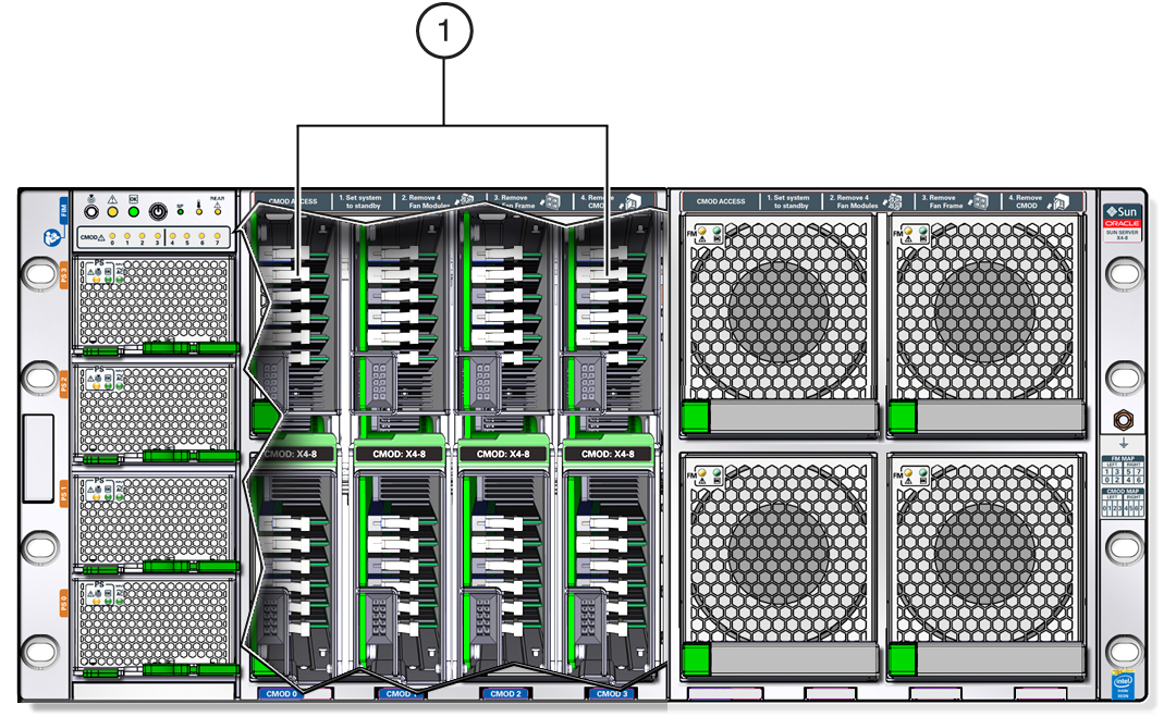
The following illustration shows a server with a four-CMOD configuration. In the illustration, the left side fan modules and fan frame have been removed to show the four CMODs. Call out 1 identifies the group of four CMODs.

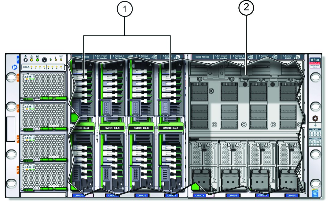
The following illustration shows a server with a four-CMOD configuration and all eight fan modules and both fan frames removed, exposing the empty CMOD bay on the right. The four right-side fan modules are not powered; however, in a four-CMOD configuration, these fan modules must be installed. Call out 1 identifies the group of four CMODs installed on the left side of the server. Call out 2 identifies the empty CMOD bay on the right side of the server.

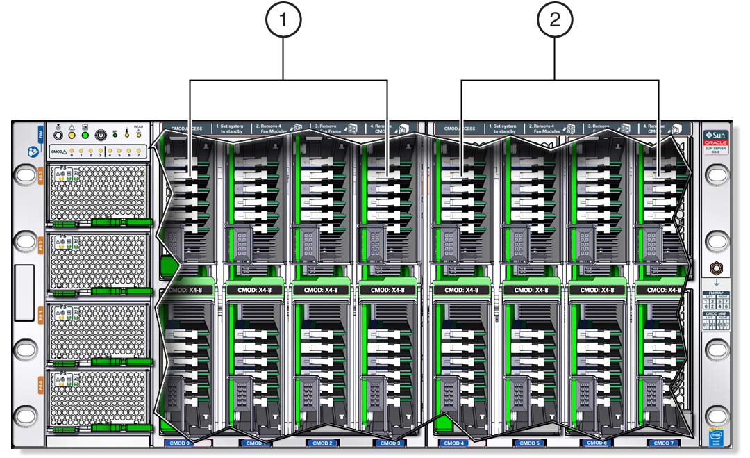
The following illustration shows a server with an eight (full) CMOD configuration. Call out 1 identifies the group of four CMODs installed on the left side of the server, and call out 2 identifies the second group of four CMODs installed on the right side of the server.

In both CMOD configurations, the system includes four power supplies, eight fan modules, and eight DPCCs. However, fan modules and DPCCs receive power from the CMODs, so in a four-CPU configuration, where CMODs are installed in slots 0-3, only fan modules 0-3 and DPCCs 0-3 are active. Fan modules 4-7 and DPCCs 4-7 are not powered and not active.
CMOD Population Rules
For the four-socket server configuration:
-
CPU modules (CMODs) must be installed in slots 0-3.
-
DPCC slots 0-3 are active.
-
Both fan frames must be installed.
-
All eight fan modules (FMs) must be installed (only FMs 0-3 are active).
For the eight-socket server configuration:
-
CPU modules (CMODs) must be installed in slots 0-7.
-
DPCC slots 0-7 are active.
-
Both fan frames must be installed.
-
All eight fan modules (FMs) must be installed (all FMs are active).
CMOD Layout
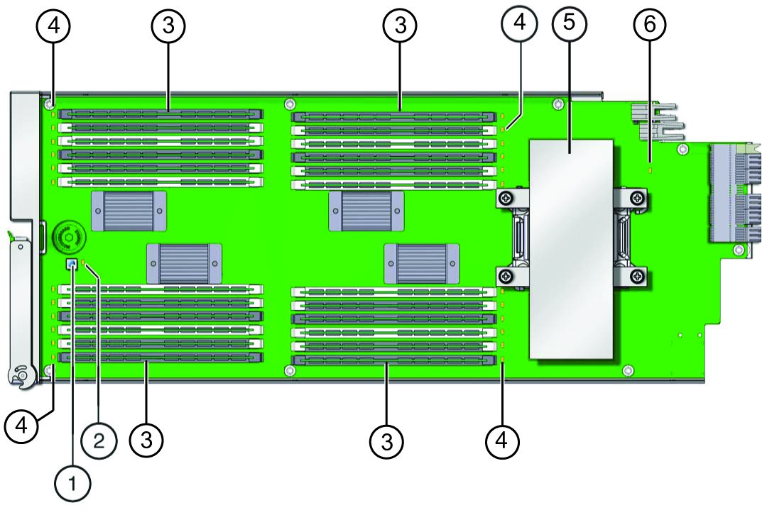
Each CMOD contains the following components:
-
Heatsink and processor assembly
-
24 DIMM slots arranged in four groups of six
-
DIMM test circuit, which helps you locate failed DIMMs and verify a failed CPU
-
Fault Remind button
-
Circuit Charge Status indicator
-
24 DIMM slot fault indicators
-
CPU fault indicator
-
The following illustration shows the location of the CMOD components.

|
For component serviceability, locations, and designations, see About System Components.
CMOD and Fan Module Power
Fan modules (FMs) get power from CMODs. However, only CMODs in certain slots supply power to fan modules. The following table shows which CMOD slots provide FM power.
|
CMODs in slots 1, 3, 5, and 7 do not supply FM power.