
If a Corente Virtual Services Gateway becomes unreachable by its partners due to connection, router, or local loop problems, you can provide alternate methods for partners to reach each of the Location's User Groups and applications. This is referred to as Traffic failover, which can be configured on the High Availability tab.
To use traffic failover, choose one or more Location gateway(s) in your application network to function as a Backup Location gateway for each User Group and/or application of this Location gateway (herein referred to as the Primary Location gateway). If a tunnel or connection fails to the Primary Location gateway, users at the partner Locations can continue to access necessary corporate resources by utilizing a tunnel to the Backup Location gateway.
A Primary Location gateway and its Backup Location gateway(s) must never be configured as application network partners.
Traffic failover can be arranged as follows to provide high availability for the connections in your application network:
Collocated Primary and Backup Location Gateways
Traffic failover can be used to provide an entirely redundant connection to a LAN. In this scenario, the Primary and Backup Location gateway(s) are installed on the same LAN, but connected to separate WAN routers, separate physical local loops, and separate carrier clouds. If the Primary Location gateway becomes unreachable because one or more of these elements fail, remote sites connecting to the Primary Location gateway can fail over to their connections to the Backup Location gateway. Additionally, all computers on the LAN participating in the application network automatically reroute to the Backup Location gateway for application network access, as well.
Primary and Backup Location Gateways on Different LANs
Enterprises can use traffic failover to recover in the event that a hub site goes down. If a hub site fails, the remote sites can use one or more Backup Location gateway(s) located at one or more other site(s) to reach their necessary subnets/resources. For example, the site of a Backup Location gateway may contain the same necessary resources that the main hub site contained (i.e., if it is a mirror site or disaster recovery center) or the site of the Backup Location gateway may have routing infrastructure that can route to the Primary Location gateway's LAN through alternate means (such as a frame relay service, ATM, or private line).
In both scenarios, for partners to use a Backup Location gateway's tunnel to connect to computers behind the Primary Location gateway, routers must be in place behind both the Primary Location gateway and the Backup Location gateway. The router behind the Primary Location gateway must be configured with alternate routes for application network traffic to the Backup Location gateway, while the router behind the Backup Location gateway must be configured to recognize the subnets behind the Primary Location gateway and route any traffic destined for those subnets to the appropriate location (either mirrored subnets or the real subnets [if a non-application-network connection to the Primary Location gateway's LAN is present]). If the Primary Location gateway itself has not failed, it will recognize that its application network tunnels are down and will poison its application network tunnel routes so that its subnets route their application network traffic to the Backup Location gateway, which in turn will route that traffic over its own application network tunnels to the appropriate partners.
Additionally, partners of the Primary Location gateway must also be partners of the Backup Location gateway, so that if tunnels to the Primary Location gateway fail, the partners can reach the Primary Location gateway's LAN or mirrored subnets through their tunnels to the Backup Location gateway. Remember, though, that a Primary Location gateway and its Backup Location gateway must never be configured as application network partners.
If you would like, you can choose to fail tubes directly over to a private backbone instead of failing User Groups over to an alternate application network tunnel via this interface. For more information, refer to Section 1.10, “Partners”.
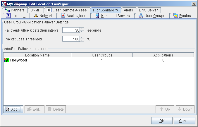
User Group Failover Settings
In this section, specify the general parameters that will apply to traffic failover for this Primary Location gateway. On the Partners tab, you can specify settings for each partner that will override these settings (see Section 1.10, “Partners”).
Failover/Failback detection interval (secs): The period of time that the partner of this Location gateway will wait until it fails over to a Backup Location gateway when it detects that the connection to this Location gateway is down. Also, the period of time that the partner will wait after it detects that the connection to this Location gateway is back up before it reverts to the connection to this Location gateway. The default is 30 seconds.
Packet Loss Threshold (percent): The minimum percentage of packets that must be lost to cause the partner to detect a failed connection. The default is 100%.
Add/Edit Failover Locations
Each Location gateway can have a Backup Location gateway that will be used by this Location gateway's partners if their connection to this Location gateway should fail. All of the current failover configurations that you have created will be displayed in this table. You can Edit or Delete any of these existing failover configurations.
Only one Backup Location gateway will be used at a time for traffic failover, but you can define multiple Backup Location gateways for each Primary Location gateway, so that several options for failover will be available in case a connection outage is widespread. Using the Up and Down buttons, you can arrange your administered Backup Location gateways in the order that you would like them to be tried when a failure of this Location gateway's connection occurs.
To add a new failover configuration, click the Add button.
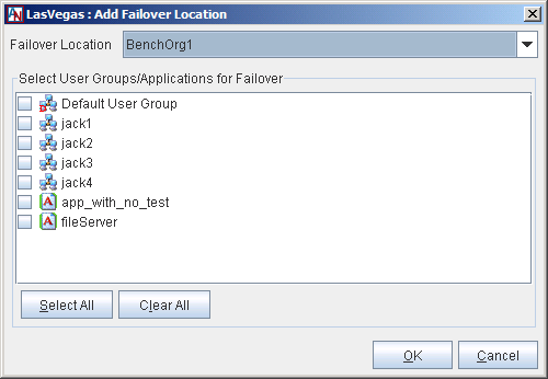
Fill out the fields as follows:
Failover Location: Select the Location gateway from this pull-down menu that you would like to function as the Backup Location gateway. This menu will contain every Location in your application network that is not a partner of this Location gateway.
Select User Groups/Applications for Failover: Choose the User Groups and/or applications that will use the selected Location as a Backup Location gateway. When a Backup Location gateway is being used for failover, all User Groups and applications that you choose here will use that Location gateway to reach necessary resources.
When you have finished, click the OK button to store your changes or the Cancel button to discard your changes.
Load Balancing with Failover
If you would like to let hub sites with multiple Location gateways manage application network traffic by allowing these Location gateways to support the same User Groups and applications, you can use the High Availability tab in conjunction with the Partner for Failover Only option on the Partners tab (Section 1.10, “Partners”). Select this option to use a Location gateway partner as a Backup connection to a site if the connection to the Primary Location gateway partner at that site should fail.
To use this option, begin by configuring the Primary and Backup Location gateway(s) for a hub site. Each Location gateway requires a separate, distinct personality file, but the personality files can include identical User Group and/or application definitions. Both the Primary and Backup Location gateways of the hub site should be partnered with the Locations that must connect to this site. Additionally, the Primary Location gateway must have the Backup Location gateway selected as the Backup Location gateway on its High Availability tab for one or more User Groups/applications. Next, when configuring the Locations that must connect to this site, select both the Primary and Backup hub site Location gateways as partners, but select the Partner for Failover Only option for the Backup Location gateway(s). This Location will now connect to the hub site through the Primary Location gateway until a failure scenario occurs, and then will be able to connect to the same site through the Backup Location gateway.
Traffic Failover and Automatic Routing Protocols
Some considerations must be made when enabling traffic failover and automatic routing protocols (RIP, OSPF, and/or BGP) at the same time in a datacenter. To illustrate, consider the example of Gateway A and Gateway B, located within the same datacenter, and Gateway C, which is located at another site.
In the simplest case, Gateway A is partnered with Gateway C. Gateway B is partnered with Gateway C as a Partner for Failover Only, for a backup route to the datacenter (see Section 1.10, “Partners”, for more information about this option). As failover (or failback) occurs, routes for Gateway C are automatically advertised on Gateway A or Gateway B (whichever is currently up). Advertisement of new RIP, OSPF, and/or BGP routes will be automatic; just ensure that the autorouting protocol you are using (RIP, oSPF, and/or BGP) is turned on for the routers at the datacenter.
However, if Gateway A and Gateway B are both ordinary partners of Gateway C (i.e., neither is Partner for Failover Only), and Gateway B is configured as a backup for Gateway A’s applications and/or subnets on Gateway C, the same automatic advertisement will not work because Gateway A and Gateway B are in the same datacenter. You can only have one gateway (A or B) communicate with Gateway C at a time, because routes will be advertised on the LAN from both A and B to C at the same time. This can be resolved by weighting the RIP, OSPF, and/or BGP routes so that Gateway A is favored, in which case, failover and auto-advertisement of routes will occur correctly. For more information about using the automatic routing protocols (RIP, OSPF, and BGP) with Corente, Section 1.5.5, “Enable RIPv2, OSPF, and/or BGP”.
Interaction of High Availability Features
The following chart describes what high availability features can be enabled when other high availability (or miscellaneous) features are also enabled. Each cell marked with an “X” denotes that the two features can be enabled at the same time.
Table 1.3 Interaction of High Availability Features
Dual WAN | Hardware Failover | Traffic Failover | Port Forwarding | WAN Alias Addresses | WAN Connectivity via PPPoE | |
|---|---|---|---|---|---|---|
Dual WAN | NA | X | X | |||
| Hardware Failover | NA | X | X | X | ||
Traffic Failover | X | X | NA | X | X | X |
Port Forwarding | X | X | X | NA | X | X |
WAN Alias Addresses | X | X | X | NA | X | |
| WAN Connectivity via PPPoE | X | X | X | X | NA |