
- 1.4.1 Location
- 1.4.2 Change the Location
- 1.4.3 Require Administrator Approval for Partner Connections
- 1.4.4 Choose a Maintenance Time
- 1.4.5 Enable Remote Logging (System Logging)
- 1.4.6 Enable Redundant Hardware Configuration (Hardware Failover)
- 1.4.7 Enable Zero Touch Installation
- 1.4.8 Disable Advanced Performance Tuning
Use this screen to add general location and personality information about your new Corente Virtual Services Gateway.
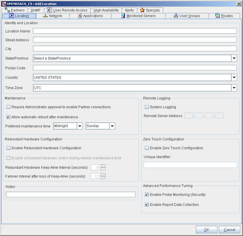
The Identity and Location section captures information regarding the name and physical location of your new Corente Virtual Services Gateway. You provided this information when creating this Location with the Location Wizard, but—except for the Location Name, which can never be changed—you can modify this information at any time.
The Maintenance section allows you to ensure that the new Corente Gateway cannot connect to its partners until an administrator has granted explicit approval to the connections in App Net Manager.
Require Administrator approval to enable Partner connections: By checking the box, you will require that the Corente Services Gateway is approved by an administrator in App Net Manager before it is fully operational.
When Require Administrator approval is selected for a new Location gateway on the Location form and the configuration file for the Location gateway is downloaded, the new Location gateway is active but unable to connect to any of its partners. However, it is in communication with the SCP while it waits for approval, so that connection to its partners can begin immediately following approval. The gateway icon is marked with a black triangle (
 ) to signify that approval is required.
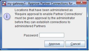
To approve the Location gateway, an administrator must right-click the Location gateway’s icon in App Net Manager and select Approve Partner Connections. The Approve Partner Connections window will be displayed. Enter your login password and click Approve to approve the connections.
Approval will be required again if the configuration is ever regenerated and re-downloaded.
By leaving the box unchecked, the Location gateway will become operational and connect to its partners immediately following configuration download.
The Maintenance section allows you to specify a time when your network is least busy so that it can be interrupted for upgrades without affecting your business.
Allow automatic reboot after maintenance: You selected your preference for this function in the Location Wizard, but you can change your choice at any time.
Preferred maintenance time: By default, maintenance will be performed on Sunday at midnight. If you would like, you can select another day of the week and an hour when your network is least busy and when an upgrade could be performed safely.
Remote Logging panel allows you to specify a server on the Location gateway’s LAN that will capture log messages from the Location gateway. System logging records all system log messages on the external server. The system log is normally recorded on the Location gateway itself. However, with remote system logging, the Location gateway will track and send all firewall log events to be recorded on the server that you specify. This is a traditional firewall log; a message is sent whenever a packet is denied from passing through the Location gateway. Each message describes a single event.
An example message is as follows:
Aug 4 14:43:26 172.18.2.1 kernel: IN=eth0 OUT= NFMARK=0xff000000
MAC=00:40:ca:1f:ea:ba:00:d0:b7:81:7e:09:08:00 SRC=172.18.2.20
DST=172.18.2.1 LEN=60 TOS=0x00 PREC=0x00 TTL=64 ID=18251 DF PROTO=TCP
SPT=3890 DPT=113 WINDOW=32120 RES=0x00 SYN URGP=0
Broken down, the relevant information in this message is the following:
Aug 4 14:43:26 - The month, date, and time when the log message was received by the remote syslog daemon.
172.18.2.1 - The IP address from where the log message came (i.e., the Location gateway).
IN=eth0 - The network device that the firewalled/blocked packet was traveling towards.
OUT= - The network device that the firewalled/blocked packet was traveling from (note that in this message, it is blank because the Location gateway blocked it while it was traveling inbound.
SRC=172.18.2.20 DST=172.18.2.1 - The source and destination IP addresses of the offending packet.
LEN=60 – The length of the packet.
PROTO=TCP - The protocol (in this case, it is TCP).
SPT=3890 DPT=113 - The source and destination port numbers of the offending packet.
SYN - In accordance to the TCP protocol, this packet is a SYN and is trying to open a new TCP connection.
To enable remote logging, you must first supply a logging server that has been configured correctly to accept a syslog feed. After this logging server is connected to the LAN and booted, fill in the Remote Logging section on the Location tab as follows:
System Logging: Select this option to send all system log messages to an external server.
Logging Server Address: When either log option is selected, you must enter the IP address of the logging server in this field. All log messages will be sent to this server.
Hardware redundancy provides a site with a backup connection to the application network that will be used in the event of a hardware or software failure of the site's active connection. By default, this service is unavailable; it must be purchased in order to be used on your Corente application network.
Redundant hardware requires each participating Location gateway server to have an additional, dedicated Ethernet interface. (This means that Location gateways using the Peer configuration must have at least two Ethernet cards, and gateways using the Inline configuration must have at least three Ethernet cards.) The two gateways will be connected via these Ethernet interfaces. You can do this using either a VLAN on a router or a dedicated hub. The Ethernet interfaces for the two Location gateways will be on their own subnet (1.1.1.1/30).
The Active and Standby Location gateways require only one configuration file to be used between them. The Location gateways must both be connected to the LAN and to the same Internet Access Device, and share a set of IP address(es) and MAC address(es) for their LAN and WAN (or LAN/WAN) interface(s). The configuration file must be manually installed on the first Location gateway server. Make sure a monitor/keyboard is connected to this server. Also ensure that the router or hub to which the two Locations gateways will connect is turned on. When the first Location gateway reboots, the installation interface will ask to identify the MAC address of the backchannel port being used for redundant hardware:
This is to configure the backchannel network interface port for the hardware failover. Now please
disconnect all network cables to this gateway machine. Identify the network port that is dedicated
to the hardware failover. Using a cable, connect the dedicated port to a hub, switch, or an active
network device. Make sure you see the 'link' light of the network port is on. Select 'Continue' to
continue with the Backchannel Configuration.
After following these directions, make sure both servers are connected to the LAN, hub or router, and have access to the Internet. Next, the software should be loaded onto the second server. Make sure a monitor/keyboard is connected to this server. This server will reboot, and the Failover Configuration option must be selected on the installation interface. The configuration will then load onto the second server, and the installation interface will ask to identify the MAC address for this server as well.
When a software upgrade occurs (during the Preferred Maintenance Time that is chosen on the Location tab), the Location gateway hardware that is currently Active will be upgraded first. Once the upgrade has completed, the hardware will alternate and the Standby Location gateway will become Active so that it can be upgraded as well. (This may cause multiple upgrade and tunnel up/tunnel down alerts, because the Location gateway that is upgraded first will attempt to re-establish its tunnels before the hardware switch occurs.) Before it becomes the Standby Location gateway, it will bring the tunnels down again. Once the second Location gateway has completed the upgrade, it will establish the tunnels and remain as the Active Location gateway until the next hardware switch occurs.
To begin configuring hardware failover, use the Redundant Hardware Configuration section on the Location tab. This section captures your preferences if you would like a Corente Virtual Services Gateway to be redundant. Fill in this section as follows:
Enable Redundant Hardware configuration: Select this option to enable hardware redundancy. If this option has been enabled, the following additional options will be available:
Enable scheduled hardware switch during weekly maintenance window: Select this option if you would like the Location gateways to rotate weekly between which Location gateway is designated as the Active and which as the Standby, so that each piece of hardware can be regularly confirmed to be functioning correctly. This switchover will occur during the weekly Preferred Maintenance Time that is chosen on the Location tab for this Location.
The following settings allow you to specify the timing of the failover intervals:
Redundant Hardware Keep-Alive Interval (seconds): The interval of time between each "heartbeat packet" that is sent by the Standby Location gateway to the Active Location gateway to make sure that the Active Location gateway is still functioning. The default is 60 seconds, with a maximum of 600 seconds.
Failover Interval after loss of Keep-Alive (seconds): The period of time that the Standby Location gateway will wait to initiate failover if the Active Location gateway has not responded to its "heartbeat" packet. This variable must be set at least twice the amount of time as the Redundant Hardware Keep-Alive Interval; therefore, the default is 120 seconds, with a maximum of 1200 seconds.
Every 10 attempts, the Redundant Hardware Keep-Alive Interval will be doubled, maxing out at 600 seconds. If this makes the interval longer than the Failover Interval after loss of Keep-Alive, then that interval will be doubled as well, maxing out at 1200 seconds. Upon success (or a restart after a failover), both intervals will revert back to the initial configured time.
After completing this section, make sure that your equipment has been prepared and connected as described in this section.
For more information about installing the gateways for hardware redundancy, refer to the II A. Corente Virtual Services Gateway Hardware Preparation and Deployment manual.
NoteYou cannot enable the Dual WAN feature (see WAN Secondary Interface) when the Redundant Hardware configuration is enabled. For more information on what features can and cannot be used when hardware failover is enabled, refer to Interaction of High Availability Features.
Zero Touch Installation allows you to install a new Corente Gateway simply by placing a server loaded with the Corente software on the network and turning it on.
When installing a new Corente Gateway, the configuration file is downloaded upon the first reboot after software installation. If there is no configuration file found on a floppy, a USB, or on the hard drive, the new Location gateway will attempt to acquire a dynamic IP address via DHCP. To utilize Zero Touch Installation, the Location gateway must be able to connect to the Internet, and the DNS server must be able to resolve “www.corente.com” to the Corente SCP. Communication between the new gateway and the SCP is secured using the HTTPS protocol.
Zero Touch Installation cannot be used when the following IP addressing options are used for the WAN (Inline configuration) or WAN/LAN (Peer configuration) interfaces of the Corente Gateway: static IP address, PPPoE, or a SOCKS proxy server (WEB Proxy will work). These options may be used for normal operation of the Location gateway, however they cannot be used to download the configuration via Zero Touch Installation.
Enable Zero Touch Configuration: Select this option to enable Zero Touch Configuration.
Unique Identifier: Enter the unique identifier for the Location gateway. You need only enter one unique identifier – either a service tag or a MAC address of one of the Location gateway’s Ethernet interfaces. The Corente software reads the service tag and all MAC addresses from the Location gateway server and passes all of them to SCP, which then matches the identifier with the appropriate configuration file.
You can disable the options in this section to improve the throughput of the gateway by suppressing potentially compute-intensive side processes.
Enable Probe Monitoring (Security): Select this option to enable the Location gateway to determine if hostile network probing is happening through the network. When deselected, probe monitoring is disabled and notifications will not be sent.
Enable Report Data Collection: Select this option to enable the collection of data for reports and graphs, such as bandwidth reports. When deselected, the gateway does not collect and present this data in App Net Manager.