
To choose Location partners and establish secure tunnel connections in your application network, access the Partner tab of the Location form for each of your Corente Virtual Services Gateways.
Using the Partners tab allows you to enable advanced functionality that is not available when using the Partner Locations Wizard (see Section 2.4, “Partner Locations Wizard”), but you must remember to configure the Partners tab for each Location involved in the partnership. Location partnerships are reciprocal and must be defined on both sides of the partnership.
The Partners tab can also be used to configure an optional Internet firewall for your LAN and to limit which local and remote computers will have access to this Location gateway to perform such functions as monitoring it with SNMP or connecting to its Gateway Viewer application.
Follow this procedure to create tunnel connections using the Partners tab of the Location form.
Access the Location form for a Corente Virtual Services Gateway:
Right-click on the Location icon in the map or domain directory and select Edit.
Double-click the Location name in the domain directory .
Select the Location name in the domain directory and then select the Edit option from the tool bar or the Edit menu.
The Location form will be displayed in a new window.
On the Location form, click the Partners tab. This tab is used to select the Locations (both Intranet and Extranet) and Corente Clients that will partner with this Location.
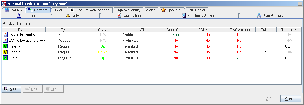
The main Partners tab presents a table of all partners that you have already added as well as four default partners: LAN to Internet Access, LAN to Location Access, DMZ to Internet Access, and LAN to DMZ Access. You may Edit or Delete any partner listed in the table. For information about the LAN to Internet Access and LAN to Location Access partners, refer to Appendix B, Additional Tube Configurations. For information about the DMZ to Internet Access and LAN to DMZ Access, refer to Appendix C, Implementing a DMZ with Corente.
This table also displays basic information about each partner:
Name: The name of the partner.
Type: The type of partner (Regular, Access, Extranet, Client Group).
Status: The current status of the tunnel between this Location and the partner.
NAT: The NAT setting for the tunnel between this Location and the partner.
Conn Share: Whether or not Connection Sharing is enabled for this partnership.
SSL Access: Whether or not SSL Access is enabled across the tunnel for this partnership.
DNS Access: Whether or not DNS Access is enabled across the tunnel for this partnership.
Tubes: The number of tubes that are defined for this tunnel.
Transport: The protocol encapsulating the packets that travel between these partners over the secure tunnel (UDP or TCP). This is determined automatically by the Location gateway. UDP is the preferred protocol, as it performs better under conditions where there is packet loss, but TCP will be used in cases when UDP cannot.
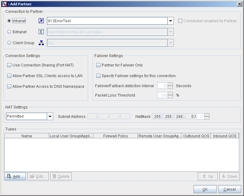
Select the Add button on the main Partners tab. The Add Partner screen will be displayed.
Begin by filling out the Connection to Partner section. This section allows you to choose a partner for this Location. To begin, you must choose one of the following types of partners:
Intranet: These are Locations within this Location's own domain.
Extranet: These are Locations from another domain that have been imported into this domain with the Extranet Imports and Exports feature (available in the domain directory) and have been permitted to contact this Location. For more information about extranets, refer to the III. Corente Services Administration manual.
Client Groups: These are groups of Corente Clients that were created with the Client Groups feature and have been permitted to access this Location. For more information about Clients, refer to the VI. Corente Services Client manual.
After selecting the type of partner you want to connect with this Location, select a Location (or client group) from the adjoining pull-down menu. If the Location has already enabled a connection to this Location on its Partners tab, the Connection Enabled by Partner checkbox will be checked. (Note that connections to client groups are defined on the Location side of the partnership only, so this checkbox will always be checked when adding a client group as a partner.)
The Connection Settings section, allows you to define this Location's parameters for the partnership.
Use Connection Sharing (Port NAT): Checking this box will cause all computers on the internal network to use the Location gateway’s IP address and some unused port of the Location gateway’s external interface as the source address and port numbers for any traffic destined for the selected partner (for Inline Locations: the WAN IP address of the Location gateway will be used for the LAN to Internet Access partner, and the LAN address will be used for the all other partners). When packets return to the Location gateway from the partner, the destination address and port are converted back to the original source address and port number pair. The Location gateway will handle the WAN IP address to internal IP address conversions automatically. (This option is especially useful for Extranet connections, when you would like to hide your internal network from an untrusted partner.)
Allow Partner SSL Clients access to LAN: Select this option if you want to allow the SSL Clients of this partner to connect to this Location and the computers within the Default User Group of this Location. For more information about this option, refer to the VII. Corente Services SSL Client manual.
Allow Partner Access to DNS Namespace: When this Location is configured as a DNS Server or a DNS Updater on the DNS Server tab and the partner is configured as a DNS Server or DNS Updater, select this option to share the DNS records of this Location with the partner. The partner will be allowed to perform lookups for the DNS names registered with this Location even when the partner is not in the same DNS zone.
When the partner is configured as a DNS Updater:
If the Locations are in separate DNS domains, the DNS records must be manually forwarded from the DNS Updater to the DNS servers it is updating.
If one is in a subdomain of the other (e.g., this Location is configured as a DNS Server and is in the subdomain of its partner, which is configured as a DNS Updater), Corente DNS will automatically forward the DNS records from the DNS Updater to the DNS servers it is updating.
ImportantIf any NAT (Outbound or Inbound) is being performed for this partner, then the Perform DNS/WINs NAT Fixup option must be selected on the Network tab of this Location.
Partner for Failover Only: Select this option to use the selected partner as a Backup connection to a site if the connection to the Primary partner at that same site should fail. This option allows hub sites with multiple Location gateways to use load balancing to manage application network traffic by allowing multiple Location gateways to support the same User Group and applications. For more information about load balancing with High Availability tab, refer to Load Balancing with Failover.
Specify Failover settings for this connection: Failover is configured on the High Availability tab of this form (for more information, refer to Section 1.13, “High Availability”. You can select this option to override the settings that you enter on the High Availability tab and define the failover behavior for the selected partner's connection to this Location only. You may want to override the High Availability tab settings and, for example, make the Failover/Failback detection interval (secs) longer on this screen if this partner uses a slower Internet connection or DSL (where short connection outages are common). When this option is selected, the following fields will be enabled and the default entries can be modified:
Failover/Failback detection interval: The period of time that the partner will wait until it fails over to a Backup Location gateway after it detects that the connection to this Location gateway is down, and the period of time that the partner will wait after it detects that the connection to this Location gateway is back up before it reverts to this connection. The default is 30 seconds.
Packet Loss Threshold: The minimum percentage of packets that must be lost to cause the partner to detect a failed connection. The default is 100%.
The NAT Settings section allows you to choose the NAT option for this partner. The setting that you select will apply to this partner only and will interact with the Outbound NAT settings that have been selected for the partner's Default User Group on the partner's User Groups tab (for more information, refer to Section 1.8, “User Groups”. The NAT options are as follows:
Prohibited: This setting prohibits the partner from performing Outbound NAT. When you select this option for the partner, the partner cannot perform Outbound NAT on any of its own subnets that are included in the User Group(s) being exported to you. No tunnel will be built and a Configuration Alert will be generated if the partner attempts to NAT its own User Group(s).
Permitted: This is a passive setting. The Location gateway will not NAT this partner's User Group(s), but it will not prevent any address ranges from being NATed by the partner. This setting can be overridden by any other NAT setting. (This is the default setting.)
Auto Resolve: If your Location gateway detects a conflict between an address range in the local User Group(s) that you are sharing with the partner and an address range in the partner's User Group(s), your Location gateway will attempt to resolve the conflict by automatically re-mapping the conflicting remote range to a new address space when this setting is selected. The NATed IP addresses will only be visible by local computers; the remote computers will not know that they have been NATed. When there is no address conflict with the partner, the Auto Resolve setting will function like the Permitted setting. To solve direct address conflicts between two partners, both partners must enable Auto Resolve NAT for each other so that address conflicts are resolved on both sides of the connection. Additionally, both partners can only have Outbound NAT settings of Permitted or Specified in their Default User Group.
If the local Location gateway runs out of address space to resolve remote ranges to, the tunnel will not be established and will appear in the Configuration Alert state. An alarm notification will be sent to the email addresses you specify on the Alerts tab, if you choose to be notified about Configuration Alerts. Remember that an administrator cannot control what address ranges will be used when User Group(s) are NATed using Auto Resolve NAT. If you are concerned about maintaining specific IP addresses for machines on your network or on the networks of remote partners, you can use Inbound NAT to resolve IP address conflicts.
Inbound: This setting can also be used to resolve IP address conflicts. When this setting is enabled for the partner, your Location gateway will re-map all IP addresses in the partner's User Group(s) to a new set of addresses in the subnet that you specify. Unlike Auto Resolve NAT, this setting will re-map the addresses even if there are no address conflicts. The NATed IP addresses will only be visible by local computers; the remote computers will not know that they have been NATed. After selecting this option, the adjacent fields will be enabled and must be filled in. Enter the subnet and netmask to which your Location gateway will re-map the partner's User Group(s). This address space must be unique in your LAN.
Like the Auto Resolve option, to solve address direct conflicts between two partners, both partners must enable Inbound NAT for each other so that address conflicts are resolved on both sides of the application network connection. Additionally, both partners can only have Outbound NAT settings of Permitted or Specified in their Default User Group.
After you have completed these steps, you must enable at least one Tube on this partner connection (see Configure Tubes, Configure Tubes).
When you are finished with the Partners tab, click OK to close the window. After you Save your changes, remember to access the Partners tab for the other Location partner and complete this process again; all Location partnerships are reciprocal.
Configure Tubes
With the Tubes feature, you can organize the secure connection between this Location and its partner into logical tubes that regulate the access of each machine on your LAN to each machine on the remote LAN, and vice versa. (Note that a tube does not create a distinct IPSec tunnel for the traffic; a tube is simply a firewalling mechanism.)
At its basic level, a tube is a combination of a local User Group or application, a remote User Group or application, and an optional Firewall Policy that is assigned between them (defining both the inbound and outbound traffic that the local side will allow over the connection). Each set of partners can have multiple tubes defined for their secure tunnel connection, but each combination of local User Group/application and remote User Group/application can be used in only a single local definition. Tubes can be configured on connections with Intranet Partners, Extranet Partners, and Client Groups, as well as used to define an Internet firewall for the LAN, enable port forwarding of Internet traffic to servers on the LAN, restrict access from the LAN to the Location gateway, and secure a DMZ. (For more information, refer to Appendix B, Additional Tube Configurations, and Appendix C, Implementing a DMZ with Corente.
Tubes are defined separately on both sides of a Location partnership. One side inspects the traffic that it sends, while the other side inspects the same traffic upon receipt. In order for traffic to route properly over the application network, the traffic must match a tube definition on both partners. In other words, for traffic to reach its destination over the connection, the tubes defined on the partner should not conflict with the tubes defined at the local Location gateway. Note that the firewall on tubes is stateful and return traffic is allowed through both firewalls, even if the firewalls usually block that type of traffic.
The Tubes table on the Partners tab lists all of the tubes that you have already configured for this Location in the partnership. If you have multiple tubes, you can rearrange the order in which they are applied to traffic by using the Up and Down buttons. Traffic will attempt to use the tubes in the specific order in which they appear on this table. For more information about the importance of tube order, refer to Important Notes About Tubes.
You can Edit or Delete any existing tube. To add a new tube, select the Add button. The Add Tube window will be displayed. (You can also create new tubes for an existing partner-to-partner connection using the Tube Wizard. For more information, refer to Tubes Wizard.
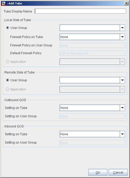
Fill out this window as follows:
If you would like, enter a name for your tube in the Tube Display Name field that will help you keep track of this tube's purpose. If you do not enter a name, the tube will be named Tube #, with “#” = numbering starting at zero (0).
The Local Side of the Tube section defines the local side of the tube.
User Group: Select User Group if you would like a local User Group to participate in this tube. Choose the User Group from the adjacent pull-down menu.
NoteIf you are creating this tube to allow a remote User Group to perform such functions as access the local Location gateway with Gateway Viewer or monitor it with SNMP, select the Location LAN Address option from the User Group pull-down menu. When selecting a Firewall Policy for this tube, make sure that:
if you are providing remote access to Gateway Viewer, the gateway_viewer Firewall Service must be allowed in this Firewall Policy.
if you are monitoring remotely with SNMP, the SNMP Firewall Service must be allowed in this Firewall Policy
When the User Group option is selected, you can define what traffic you will allow to enter and leave your LAN between the local and remote side. The following Firewall Policy option will be enabled:
Firewall Policy on Tube: Select a Firewall Policy that you would like to apply to traffic traveling between this User Group and the remote side of the tube.
Below this option will be two additional fields:
Firewall Policy on User Group: If there is a Firewall Policy that was enabled when defining the selected User Group and always applies to this User Group, the Firewall Policy will be displayed in this field.
Default Firewall Policy: The default firewall policy for this type of connection will be displayed in this field (i.e., LAN to Remote LAN, LAN to Client, LAN to Extranet LAN, etc.).
All three Firewall Policies are listed here to remind you that Firewall Policies will be enforced on the connection in this order: Tube Firewall Policy, User Group Firewall Policy, and then Default Firewall Policy.
Application: Select Application if you would like a local application to participate in this tube. Choose the application from the adjacent pull-down menu.
The Remote Side of Tube section defines the remote side of the tube. All of the partner's User Groups and applications are listed in the pull-down menus in this section, but depending on the permissions that are granted to you by this partner in its own tube definitions, you may not have access to all of them.
User Group: Select User Group if you would like a remote User Group to participate in this tube. Choose the remote User Group from the adjacent pull-down menu.
NoteIf you would like to create a tube to designate a local User Group that is allowed to perform such functions as access the local Location with Gateway Viewer or monitor it with SNMP, select the Location LAN Address option from the remote User Group pull-down menu. You should then select the local User Group that will participate in this tube. When selecting a Firewall Policy for this tube, make sure that:
if you are providing access to Gateway Viewer, the gateway_viewer Firewall Service must be allowed in this Firewall Policy .
if you are monitoring with SNMP, the SNMP Firewall Service must be allowed in this Firewall Policy.
For more information about the Location LAN Address option when it appears in the Remote User Group pull-down menu of the LAN to Gateway Access partner, refer to Appendix B, Additional Tube Configurations.
Application: Select Application if you would like a remote application to participate in this tube. Choose the remote application from the adjacent pull-down menu. this option.
The Outbound QoS section allows you to enable Quality of Service (QoS) settings to the outbound traffic on this tube. QoS settings are viewable and configurable with the Quality of Service feature (for more information, refer to Section 2.2, “Quality of Service (QoS)”.
Setting on Tube: Choose a QoS entry from the pull-down menu to specify the priority of traffic outbound from the Location on this tube.
NoteAs when performing any sort of QoS configuration, administrators must be careful when assigning QoS levels because if there is too much high priority traffic, any other traffic with a lower level of priority may become too slow or even be dropped. In addition, you cannot use QoS to prioritize traffic to or from a Corente Client.
Setting on User Group: If there is an Outbound QoS Setting that was enabled when defining the selected User Group/application and always applies to this User Group/application, the Outbound QoS Setting will be displayed in this field. This field is displayed to remind you that QoS settings will be enforced on the connection in this order: Tube QoS setting and then User Group QoS setting.
The Inbound QoS section allows you to enable QoS settings to the inbound traffic on this tube.
Setting on Tube: Choose a QoS entry from the pull-down menu to specify the priority of traffic inbound from the Location on this tube.
Setting on User Group: If there is an Inbound QoS Setting that was enabled when defining the selected User Group/application and always applies to this User Group/application, the Inbound QoS Setting will be displayed in this field. This field is displayed to remind you that QoS settings will be enforced on the connection in this order: Tube QoS setting and then User Group QoS setting.
When you have finished defining the tube, select OK to store your changes or Cancel to close the screen and discard your changes. The new tube will appear in the Tubes table.
Important Notes About Tubes
If traffic from a local User Group/application tries to reach a remote User Group/application, it will test each of the tubes defined on the local Location gateway. If its source, destination, and protocol type are allowed in the definition of any locally defined tube, the traffic will use that tube to reach the remote User Group/application. The traffic then tests the remotely defined tubes to see if its source, destination, and protocol type are permitted in any of those definitions. This continues until a match is found on both sides. If no match is found, traffic will be treated according to the Firewall Policy of the last tube and whether or not Backhaul has been enabled on the Network tab of the Location form, Section 1.5.4, “Enable Location Gateway as Backhaul Server or Client”.
It is important that the Firewall Policy of the last tube should be set to Allow if no match on selected Services or Deny if no match on selected Services (rather than Continue). When Continue is selected for the Firewall Policy of a tube, the Location gateway will continue to try and match traffic to the next tube definition. This becomes a security hazard when applied to the last tube, and could allow unwanted traffic to enter or leave your LAN. For more information about configuring Firewall Policies, refer to Firewall Policies.
When traffic reaches the last tube without finding a compatible definition:
If Backhaul is enabled, the Location gateway attempts to match the source address (if outbound traffic) or destination address (if inbound traffic) to an address included in one of the Location’s User Groups or applications. If it matches and the address does not have permission to participate in the application network or to send/receive this type of traffic, the traffic is dropped to prevent a security breach. If the address does not match any address in a User Group or used for an application, it is assumed that the user was trying to access the Internet and the traffic is sent to the Backhaul Server (if Backhaul Client is enabled) or to the Internet (if Backhaul Server is enabled). It is important to define a Special User Group for Internal Network Description on the User Groups tab for this Location when Backhaul is used, to prevent traffic from being mistakenly sent to non-application-network machines on the LAN rather than the Internet. For more information about this special User Group, refer to Section 1.8.2, “Create the Internal Network Description Group” .
If Backhaul is not enabled, the traffic is unconditionally dropped.