Using the Database Binding Component
In this tutorial, you will create a SOA project. First add a WSDL Document to the project and use the Partner View of the WSDL Editor to add the Partner Link type. You will then create a Composite Application project and use the Composite Application (Service Assembly) Editor to modify the project configuration.
For more information about working with the NetBeans IDE, see the http://www.netbeans.org page on the NetBeans web site.
What You Need to Know
These topics provide information you need to know before using the Database Binding Component.
What You Need to Do
The topics listed here provides information about Understanding the Database Binding Component (BC). The Database BC provides a comprehensive solution for configuring and connecting to databases that support JDBC from within a JBI environment.
These topics provide instructions to complete a Database Binding Component sample Project. It also helps to test the Binding Component on the system and demonstrate how it is implemented.
Tutorial Overview
This tutorial introduces a new OpenESB component that replaces two existing components.
-
The Java Database Connectivity (JDBC) Binding Component (BC)
-
The Structured Query Language (SQL) Service Engine (SE)
Tutorial Requirement
Review this section before proceeding to use this tutorial.
Software Needed for the Tutorial
GlasshFish V2.0 Installer
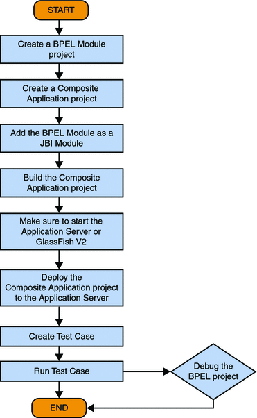
Tutorial Plan
-
Create a BPEL Module project using the New Project wizard.
-
Create the following WSDL Document for the BPEL Module.
-
DATABASE WSDL
-
SOAP WSDL
For Database BC,
Note –Test Cases are not required for projects created using File Binding Component and JMS.
-
-
Create a Composite Application project.
-
Add the BPEL Module project (*.jar) as a JBI Module to the Composite Application project.
-
Build the Composite Application project and make sure that the Application Server is started.
-
Deploy the Composite Application project to the Application Server.
-
Create Test Case.
-
Run the Test Case.
-
(Optional) Debug the BPEL process.
This is performed when the Test Case fails.
Follow this to build a BPEL process.
Downloading GlassFish ESB Installer
This topic provides information for downloading GlassFish ESB installer. The installer is available at the following location: http://open-esb.org.
For detailed information, please see the following links:
-
Installing the JDK Software and Set JAVA_HOME on the Windows System - http://wiki.open-esb.java.net/Wiki.jsp?page=Inst_jdk_javahome_t.txt.
-
Installing GlassFish ESB Using the GlassFish ESB Installer - http://wiki.open-esb.java.net/Wiki.jsp?page=Inst_caps_t.txt.
Downloading and Installing the JAR Files and the NBM Files
This topic briefly describes the method to download and install the required JAR and NBM files for Database Binding Component. Perform this procedure only when you delete the JAR file.
The JAR and the NBM files are bundled in GlassFish ESB installer. If you have deleted the .jar files from the installed location then perform this procedure.
 To Install the JAR Files in Database Binding Component
-
Download the databasebc.jar # files to a location on disk.
-
Start NetBeans IDE.
-
Click Services tab -> Servers —> GlassFish V2 -> Start.
-
Expand JBI —> Binding Components.
-
Right-click on Binding Components node and select Install to browse for the files downloaded in step 1.
-
Right-click on installed binding component and select Start.
 To Install the NBM Files in Database Binding Component
-
Download the org-netbeans-modules-wsdlextensions-jdbc.nbm files to a location on disk.
-
Start NetBeans IDE.
-
Click Tools —> Plugins.
-
Click on the Downloaded tab.
-
Click Add Plugins to browse for the files downloaded in step 1.
-
Click on Install and follow the prompts.
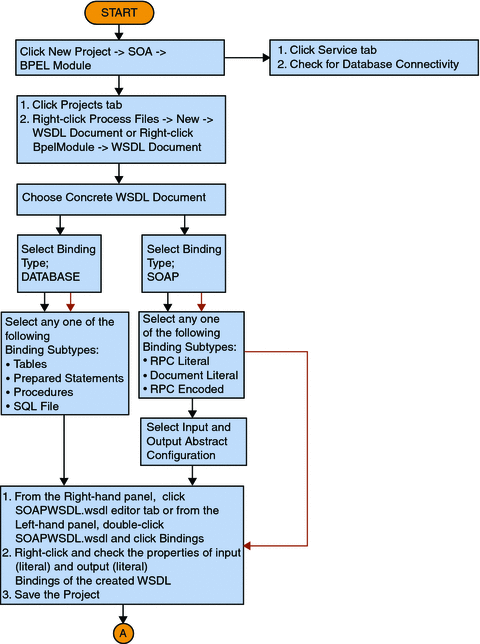
Database Binding Component Project in a Nutshell
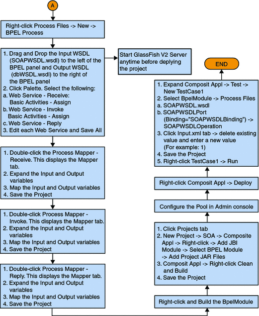
The illustration explains the entire process.
Flowchart 1
Flowchart 1 (Continued)
Starting the GlassFish V2 Application Server
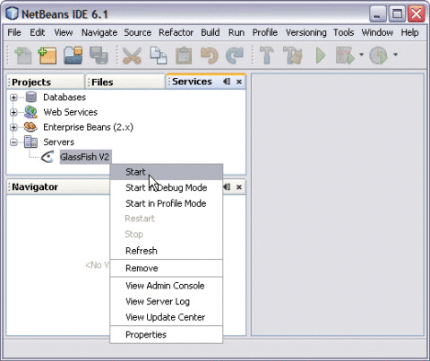
Follow the procedure to start the GlassFish V2 Application Server.
 To Start the GlassFish V2 Application Server From
NetBeans IDE
-
Choose Window —> Services, if the Services tab is not visible.
-
Click Services tab and expand the Servers node.
The Servers node should contain a GlassFish V2 subnode.
-
Right-click the GlassFish V2 node and select Start.
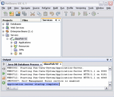
The Output window displays logging information about the application startup.
The following message appears in the Output console indicating the application server is listening.
Application server startup complete
Note –A green arrow badge on the GlassFish Application Server node indicates the server is listening.
Creating a BPEL Module Project For Table Type Operations
A table represents a database table. It consists of fields and methods. This allows you to perform query, update, insert, and delete SQL operations in a table.
-
Fields correspond to the columns of a table
-
Methods are the operations that you can apply
Create a BPEL Module project with a name BpelModuleSample.
 To Create a BPEL Module Project
-
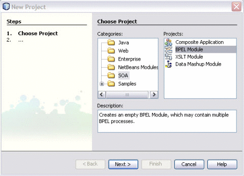
Choose File —> New Project from the main menu.
This opens the New Project wizard.
-
Select the SOA node from the Categories list.
-
Select the BPEL Module node from the Projects list.
-
Click Next.
-
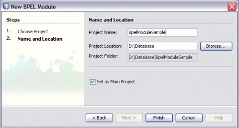
Type the Project Name in the Project Name field.
For example, BpelModuleSample
-
Click Browse to navigate to the project location field.
The IDE stores the project files. This step is optional.
-
Click Finish.
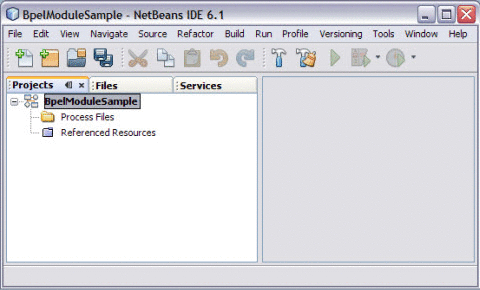
The Projects window now contains a project node for a BPEL Module project.
For example, BpelModuleSample
-
Click Save All.
Connecting to a MySQL Database
This topic demonstrates setting up a connection to a MySQL database from GlassFish ESB — NetBeans IDE 6.1.
Connections to databases are managed using database drivers, which enable applications written in different programming languages to interact with the database management system. GlassFish ESB — NetBeans IDE 6.1 comes bundled with the MySQL Native (mysql-connector-java-5.1.5-bin.jar), which is a Java implementation of the JDBC API, and communicates directly with the MySQL Driver.
 To Connect to a MySQL Database
-
Click Services tab.
-
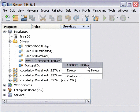
Expand the Drivers node from the Database Explorer. Right-click the MySQL (Connector/J driver) and choose Connect Using....
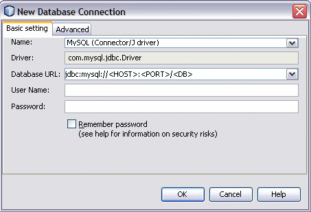
The New Database Connection dialog box is displayed.
-
In the Basic Setting tab, enter the Database's URL <HOST>:<PORT>/<DB> in the corresponding text field.
The URL identifies the type and location of a database server.
In this example, specify the host name (that is, the location of the server), the port number on which the database communicates, and the name of the database instance.
In this case you can enter: jdbc:mysql://localhost:xxxx/MyNewDatabase.
-
Enter User Name and Password.
Note –Select the Remember password option. This is optional.
-
Click OK to accept the credentials.
This displays a new Connection node in the Database Explorer under the Databases node.
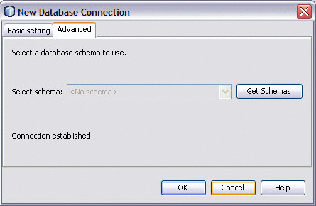
-
Click OK to accept the default schema.
-
Right-click the MySQL Database URL in the Services window (Ctrl-5). Click Connect.
This opens the New Database Connection dialog box.
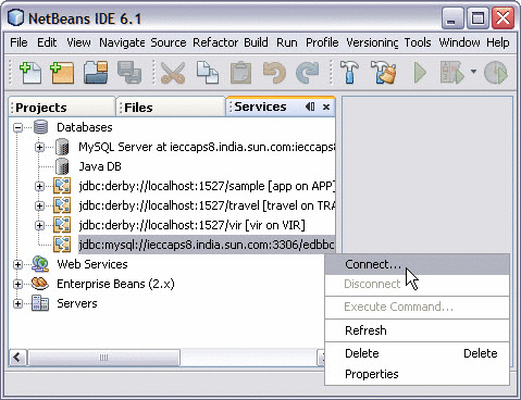
The illustration shows that the Database Connection is enabled.
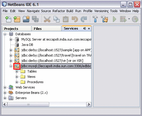
You are now connected to the MySQL RDBMS in the IDE.
Working With Administration Console
This section describes the Administration Console and introduces basic administration tasks. This section contains the following topics: Setting Up Database Access.
 To Start Administration Console
-
Open a web browser and type the following URL,
http://localhost:port/login.jsf
Note –The default port is 4848.
-
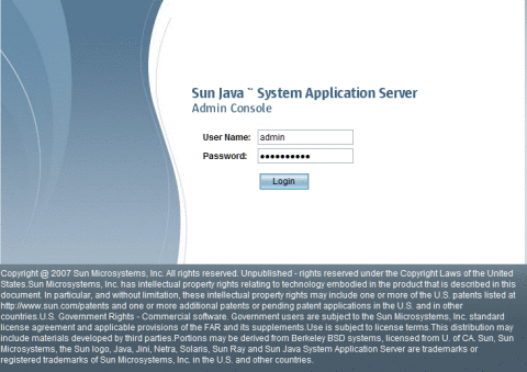
Enter the User Name and Password.
Note –The default username is admin and the default password is adminadmin.
-
Click Login.
Setting Up Database Access
Follow these steps:
-
Make the driver's JAR file accessible to the domain's server instance. See To Integrate a JDBC Driver.
-
Create a connection pool for the database. See To Create a JDBC Connection Pool.
-
Create a JDBC resource that points to the connection pool. See To Create a JDBC Resource.
Integrating a JDBC Driver
A JDBC driver translates an application's JDBC calls into the protocol of the database server.
To integrate the JDBC driver into an administrative domain, perform either of the following:
 To Integrate a JDBC Driver
-
Make the driver accessible to the common class loader.
-
Make the driver accessible to the system class loader.
Creating a JDBC Connection Pool
When creating the pool with the Admin Console, you are actually defining the aspects of a connection to a specific database. A JDBC connection pool is a group of reusable connections for a particular database. Because creating each new physical connection is time consuming, the server maintains a pool of available connections to increase performance. When an application requests a connection, it obtains one from the pool. When an application closes a connection, the connection is returned to the pool.
Before creating the pool, you must first install and integrate the JDBC driver. See To Integrate a JDBC Driver.
When creating the Create Connection Pools, certain data specific to the JDBC driver and the database vendor must be specified. Before proceeding, gather the following information:
-
Database vendor name
-
Resource type,
-
javax.sql.DataSource (local transactions only)
-
java.sql.ConnectionPoolDataSource (local transactions, possible performance improvements)
-
javax.sql.XADataSource (global transactions)
-
-
Data source class name
-
Required properties, such as the database name (URL), user name, and password
 To Create a JDBC Connection Pool
-
Select the Common Tasks node, then click Resources —> JDBC —> Connection Pool.
Note –Select New to create a new connection pool from the New Connection Pool page.
-
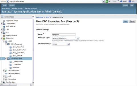
Specify the General Settings as follows:
-
Name: Specify a Name for the pool.
For example, mysqlpool
-
Resource Type: Select a Resource Type from the drop-down menu.
Choices include,
-
javax.sql.XADataSource (global transactions)
-
java.sql.ConnectionPoolDataSource (local transactions, possible performance improvements)
-
javax.sql.DataSource (local transactions only)
-
-
Database Vendor: Select a vendor from the list provided in the drop-down menu.
For example, mySQL
-
-
Click Next.
-
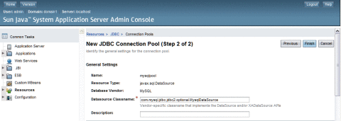
Specify the additional General Settings as follows:
-
Datasource Classname: If the JDBC driver has a Datasource class for the resource type and database vendor specified in the previous page, then the value of the Datasource Classname field is provided.
For example, MySQL : com.mysql.jdbc.jdbc2.optional.MysqlDataSource
-
Description: A text description of the connection pool.
-
-
Specify the Pool Settings.
The values are entered, by default.
-
Specify the Connection Validation.
The values are entered, by default.
-
Specify the Transaction Isolation settings.
The values are entered, by default.
-
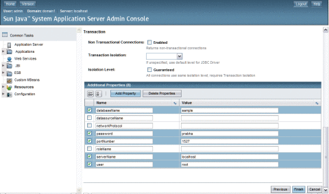
Add the required properties in the Additional Properties table, such as database name (URL), user name, and password. Enter the following.
-
Click Finish.
 To Create a JDBC Resource
Applications get a database connection from a connection pool by looking up a data source on the Java Naming and Directory Interface (JNDI) tree and then request a connection. The connection pool associated with the datasource provides the connection to the application.
Before You Begin
Before creating a JDBC resource, first create a JDBC connection pool. See To Create a JDBC Connection Pool.
-
Expand the Resources, then JDBC path node.
-
Select the JDBC Resources node.
-
Click New from the JDBC Resources page.
-
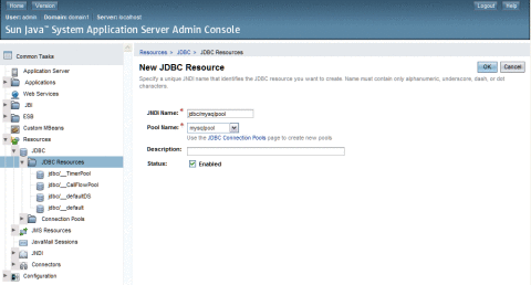
Specify the Resource settings as follows:
-
JNDI Name: Specify a unique name. The JNDI name organizes and locates components within a distributed computing environment similarly to the way that card catalogs organize and represent locations of books in a library. Consequently, the JNDI name becomes an important method of accessing the JDBC resource. By convention, the name begins with the jdbc/string.
For example: jdbc/payrolldb.
Note –Remember to give a forward slash.
-
Pool Name: Choose the connection pool to be associated with the new JDBC resource.
-
Description: Type a short description of the resource.
-
Status: If you want the resource to be unavailable, deselect the Enabled checkbox. By default, the resource is available (enabled) as soon as it is created.
-
-
Click OK.
Creating a WSDL Document For Type : DATABASE
In this section, you add a WSDL document, to the BPEL Module project and then use the Partner view of the WSDL editor to configure the components of the WSDL document.
 To Create a WSDL Document : dbWSDL
-
Expand the project node in the Projects window.
For example, BpelModuleSample
This opens the New WSDL Document wizard.
-
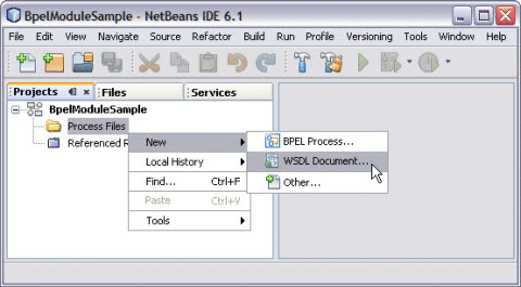
Right-click the project node or Process Files node. Select New —> WSDL Document...
For example, BpelModuleSample
-
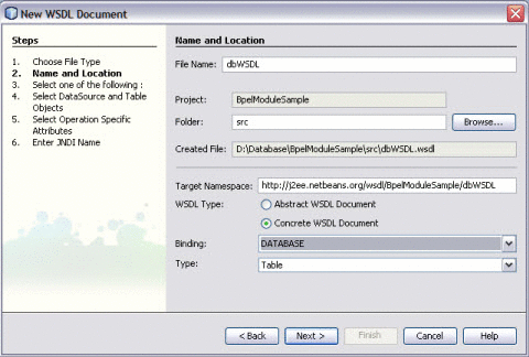
Enter the filename in the File Name field.
For example, dbWSDL.wsdl
-
Select Concrete WSDL Document.
-
binding
Defines the message format and protocol details for a port type. For JDBC Binding Component, this is always a message containing a database operation defined using the JDBC API.
-
service
Indicates which binding to use and how to access the database resource. For Database Binding Component, the address element (<jdbc:address>) specifies the JNDI name for the database resource.
-
-
Choose the Binding — Database from the drop-down list.
The Binding — SOAP is selected and displayed, by default.
-
Choose any one of the following Types from the drop-down list.
-
Table
-
Prepared Statements
-
Procedures
-
SQL File
-
-
Choose Type — Table from the drop-down list.
-
Click Next.
-
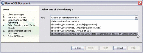
Select the URL from the drop-down list.
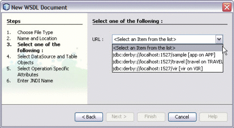
You find the MySQL Database is not configured and is not available in the list.
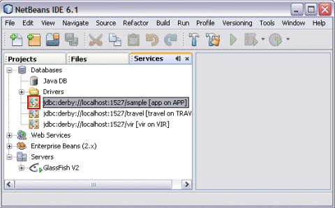
Note –A broken icon indicates that the database is not connected.
 To Select the Database Connection
Before You Begin
See To Create a WSDL Document : dbWSDL to Create the WSDL Document.
-
Select the URL from the drop-down list.
-
Click Next.
-
Select the table from the DataSource and Table Objects.
-
Click > to move the table from Available Tables to Selected Tables.
Click < to remove the table from the list of Selected Tables.
Note –You can select and move one table at a time.
ALL> and <ALL feature is not enabled. This feature will be implemented in future.
-
Click Next.
-
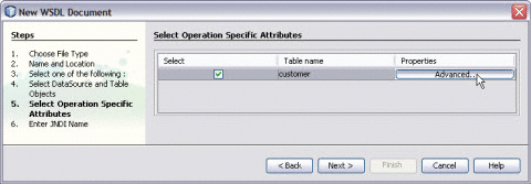
Select Operation Specific Attributes.
-
Click Advanced. Select the required Column name.
You can Insert, Update, Find, and Poll Records.
Note –As the ID is unique, they cannot be unchecked. Hence, these are greyed out.
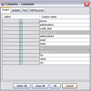
Note –Based on the requirement, you can check and uncheck the Column names.
-
Click OK.
-
Click Next.
-
Enter an appropriate JNDI Resource Name.
-
Click Finish.
Observe the following:
-
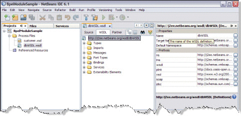
In the Projects window, the IDE adds a dbWSDL.wsdl node under the Process Files node along with the .xsd file.
-
The dbWSDL.wsdl file is open in the WSDL editor.
The WSDL editor has three views: Source, WSDL, and Partner.
-
The Properties window is open.
Note –If you do not see the Properties window, choose Window —> Properties.
-
The Navigator window is open.
-
 To Edit the SQL
-
Double-click the created WSDL Document.
For example, dbWSDL.wsdl
The WSDL Editor is opened.
-
Expand Bindings —> binding PortType=”jdbcPortype”.
For instance, you want to perform a find operation.
-
Select and expand find from the list.
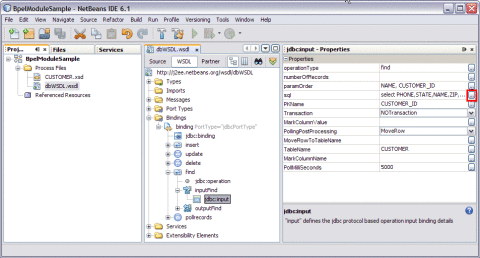
Expand inputFind and click jdbc:input.
-
Select sql from Properties.
Modify the SQL Statement.
-
Click ellipses (...).
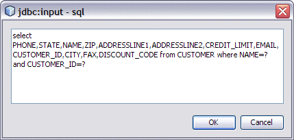
This opens the jdbc:input — sql editor.
Make the necessary changes.
For example,
select PHONE, STATE, NAME, ZIP, ADDRESSLINE1, ADDRESSLINE2, CREDIT_LIMIT,
EMAIL, CUSTOMER_ID, CITY, FAX, DISCOUNT_CODE
from CUSTOMER where NAME=? and CUSTOMER_ID=?
-
Click OK.
-
Click the paramOrder from Properties and enter the values.
For example, you want to find for NAME and CUSTOMER_ID. Enter the parameter order of the result.
See Also
WSDL View
-
In the WSDL view of the WSDL Editor, the WSDL file appears as a tree component or a series of columns.
-
The WSDL view has two subviews: tree view and column view. To switch between the subviews, use the buttons in the WSDL Editor toolbar.
-
The main nodes in the WSDL view correspond to the major elements in a WSDL file.
-
Types: This node enables you to import XML schemas and to add inline schemas.
-
Imports: This node enables you to import WSDL files.
-
Messages: This node enables you to create, edit, and delete messages.
-
Port Types: This node enables you to create, edit, and delete port types.
-
Bindings: This node enables you to create, edit, and delete bindings.
-
Services: This node enables you to create, edit, and delete services.
-
Extensibility Elements: This node enables you to add the following extensibility elements: partner link types, properties, and property aliases.
-
Some of the nodes in the WSDL view allow you to add extension attributes.
-
Right-click the node and choose Add Extension Attribute.
-
Specify the name and namespace in the Add Extension Attribute dialog box.
-
Specify the value from the Properties window after adding the attribute.
-
Right-click the node and choose Remove Attributes to delete the attribute.
-
Right-click a node and choose Go To —> Source.
The Source view appears with the cursor positioned at the beginning of the component's block.
Source View
-
The top of the Source Editor has a tab for each open document. Each tab shows the name of the document.
Note –If the document has been modified and has not been saved, then an asterisk (*) appears after the name. You can right-click a tab to access various commands.
-
A toolbar is located at the top of the Source Editor window.
-
Source code displayed in the Source Editor is syntactically colored.
-
The Source Editor status line is located beneath the horizontal scroll bar. To toggle between insert mode and overwrite mode, use the Insert key.
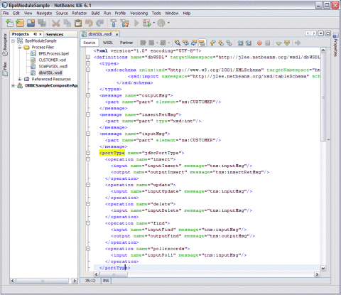
In the Source view, the underlying XML source code appears. You can directly edit the XML.
Creating a WSDL Document For Type SOAP
In this section, you add a WSDL document to the BPEL Module project. Later, you can use the Partner view of the WSDL editor to configure the components of the WSDL document.
When creating or editing a WSDL file, you may be prompted to select a binding type and a binding subtype. A binding contains protocol and data format information for the operations and messages of a port type. For more information, see step 6.
 To Create a WSDL Document : SOAPWSDL
-
Expand the project node in the Projects window.
For example, BpelModuleSample
This opens the New WSDL Document wizard.
-
Right-click the node or Process Files node. Choose New —> WSDL Document...
For example, BpelModuleSample
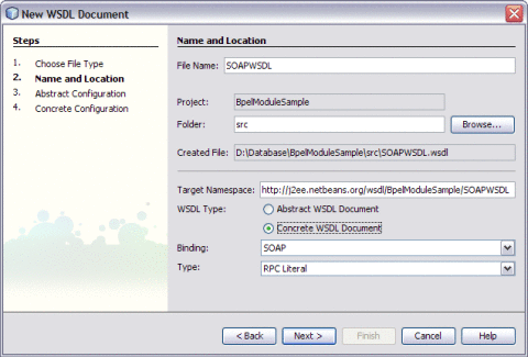
-
Enter the filename in the File Name field.
For example, SOAPWSDL.wsdl
-
Select Concrete WSDL Document.
-
binding
Defines the message format and protocol details for a port type. For JDBC Binding Component, this is always a message containing a database operation defined using the JDBC API.
-
service
Indicates which binding to use and how to access the database resource. For Database Binding Component, the address element (<jdbc:address>) specifies the JNDI name for the database resource.
-
-
Choose the Binding — SOAP from the drop-down list.
The Binding — SOAP is selected and displayed, by default.
-
Select any one of the following Type.
If you select the SOAP binding type, then you must select any one of the following binding subtypes:
-
RPC Literal: The operations are RPC oriented (that is, messages contain parameters and return values). Each message part references a concrete schema definition by using the element or type attribute.
-
Document Literal: The operations are document oriented (that is, messages contain one or more documents). Each message part references a concrete schema definition by using the element or type attribute.
-
RPC Encoded: The operations are RPC oriented (that is, messages contain parameters and return values). Each message part references an abstract type by using the type attribute.
-
-
Choose Type — RPC Literal from the drop-down list.
-
Click Next.
This action displays the New WSDL Document dialog box.
-
Choose the Operation Type from the drop-down list.
The WSDL Editor is used to create, edit, and delete port types.
The WSDL Editor supports the following categories of operations:
-
Request-Response Operation: The operation receives a message as input, and sends a message as output.
-
One-Way Operation: The operation can either receive or send a message as input.
Each message contains one or more logical parts. Specify the name and the type of content for each part.
Tip –If you change the name of a port type or operation, then the WSDL Editor renames all occurrences in the same file.
-
Right-click the component node to rename all occurrences in associated XSD, WSDL, and BPEL files.
-
Choose Refactor —> Rename.
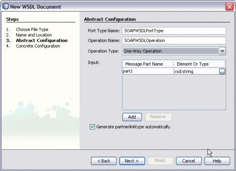
When Operation Type : One-Way Operation. The illustration is as shown.
Note –-
Click the ellipses (...) button to select any Element or Type.
-
Enter both the Input and Output Message Part Names for Request-Response Operation.
The default value of the Input and Output Message Part Names is xsd:string.
-
Click Add to another Message Part Name as the Input.
The checkbox Generate partnerlinktype automatically is selected, by default.
Note –Click Remove to delete the Message Part Name as the Input.
See Steps 11 through 15.
-
-
Select Operation Type : Request-Response from the drop-down list.
Note –Port Type Name and Operation Name are populated from the previous wizard.
-
Click the ellipses (...) to select the Element or Type.
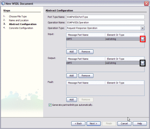
The Select Element or Type dialog box is displayed.
-
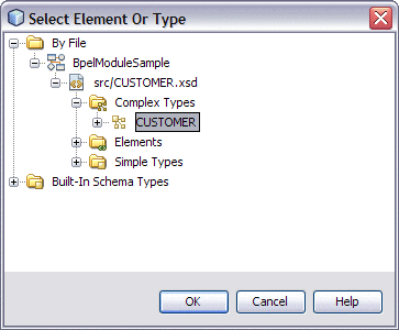
Expand By File.
-
Select the Complex Types for both the Input and Output Message Part Name.
For example, CUSTOMER
-
Click OK.
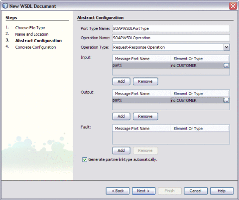
The New WSDL Document is populated with the Input and Output Element Part Names.
-
Click Next.
Verify the Concrete Configuration.
-
Click Finish.
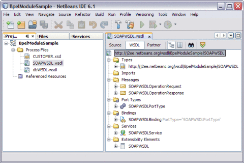
Creating a BPEL Process
In this section, you add a BPEL process file, for example, BPELProcess.bpel. Add a partner link and three activities to the BPEL process file.
 To Create a BPEL Process
-
Expand the BPEL Module project node in the Projects window.
For example, BpelModuleSample
-
Right-click the BPEL Module project name or Process Files node. Choose New —> BPEL Process...
For example, BpelModuleSample
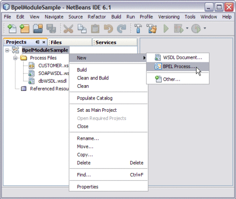
This opens the New BPEL Process wizard.
-
Type the File Name in the File Name field.
For example, BPELProcess
-
Click Finish.
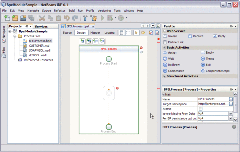
Note –-
In the Projects window, the IDE adds a BPELProcess.bpel node under the Process Files node.
-
The BPELProcess.bpel file is open in the BPEL Designer.
-
The Properties window is open.
-
If you do not see the Properties window, choose Window —> Properties.
-
The Navigator window is open showing the BPEL Logical View of the BPEL Process document.
-
 To Add a Partner Link
-
Select the Partner Link from the Projects tab.
For example, SOAPWSDL.wsdl
This is the Input WSDL.
-
Drag and drop the SOAP WSDL Document to the left panel of the design area.
For example, SOAPWSDL.wsdl
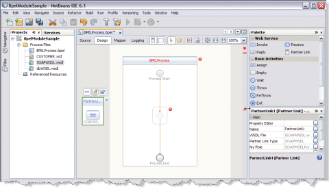
-
Select the Partner Link from the Projects tab.
For example, dbWSDL.wsdl
This is the Output WSDL.
-
Drag and drop DATABASE WSDL Document to the right panel of the design area.
For example, dbWSDL.wsdl
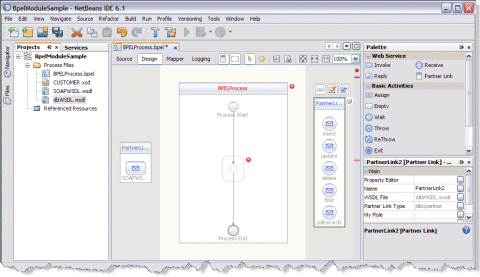
 To Add a Web Service and Basic Activities
Drag and Drop the following Web Services:
-
Receive
-
Invoke
-
Reply
Drag and Drop the Basic Activities : Assign1 and Assign2.
-
Select the Web Service : Receive in the Web Service section of the Palette.
-
Drag the selection to the BPELProcess box in the design area between the Process Start and the Process End activities.
The IDE provides the visual clues to show an appropriate location to drop the selection.
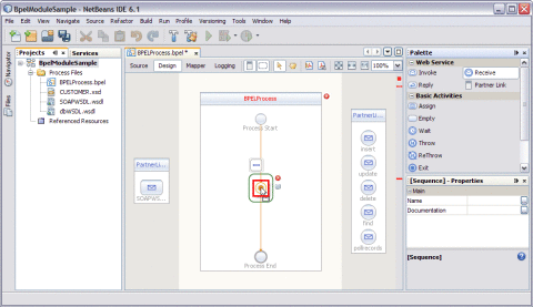
This action places a Web Service Receive called Receive1 in the Design view.
-
Select the Basic Activities — Assign in the Basic Activities section of the Palette.
This action places a Assign activity called Assign1 in the Design view.
-
Drag the selection to the BPELProcess box in the design area, between the Process Start and the Process End activities.
Note –Repeat steps 1 through 4 to select Invoke1, Assign2, and Reply1.
Choose the following:
-
Select the Web Service : Invoke and Basic Activities : Assign.
-
Select the Web Service ; Reply.
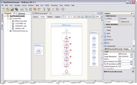
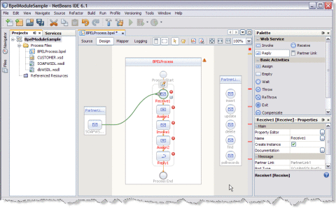
Note –In the diagram, a red cross next to an element means that the element has not passed validation and the output contains errors. Edit each Sequence to pass validation.
The icon symbolizes that the Web Services can be edited.
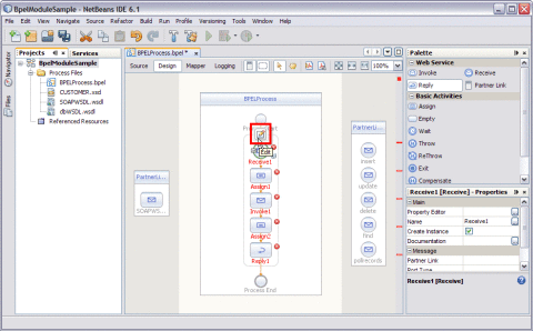
-
 To Edit Web Service : Receive1
-
Click Web Service — Receive1 and click Edit.
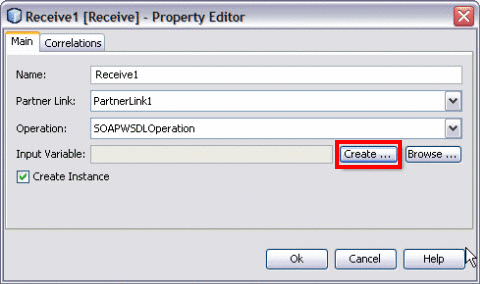
This opens the Receive1 [Receive] - Property Editor.
-
Select the properties from the Main tab. Select PartnerLink1 from the drop-down list.
The IDE fills in the Operation field with SOAPWSDLOperation.
-
Create a new input variable.
Perform the following:
-
Click the Create button next to the Input Variable field.
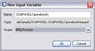
This opens the New Input Variable dialog box.
-
The Name, Type, and Scope are displayed, by default.
You can also change the value in the Name field.
-
Click OK.
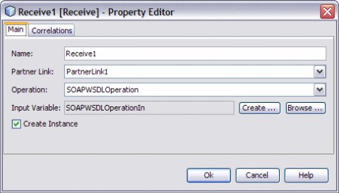
Note –All the fields are populated with the assigned values.
Input Variable — SOAPWSDLOperationIn
-
-
Click OK to close the Receive1 [Receive] - Property Editor.
-
Click Save All.
 To Edit the Web Service : Invoke1
-
Click Web Service — Invoke1 and click Edit.
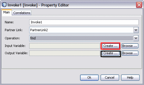
This opens the Invoke1 [Invoke] - Property Editor.
-
Select the properties from the Main tab. Select PartnerLink2 from the drop-down list.
Select any one of the Operations from the drop-down list.
-
Insert
-
Update
-
Delete
-
Find
-
Pollrecords
Select Operation — find from the drop-down list. The IDE fills in the Operation field.
-
-
Follow the steps to create a new input and an output variable.
-
Click the Create button next to the Input Variable field.
This opens the New Input Variable dialog box.
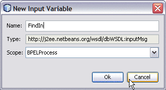
The Name, Type, and Scope are displayed, by default.
You can also change the value in the Name field.
-
Click OK to close the New Input Variable dialog box.
-
Click the Create button next to the Output Variable field.
This opens the New Output Variable dialog box.
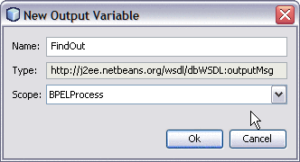
The Name, Type, and Scope are displayed, by default.
You can also change the value in the Name field.
-
Click OK to close the New Output Variable dialog box.
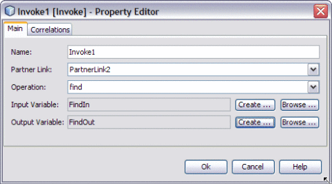
Note –All the fields are populated with the assigned values.
Select the following Variables:
-
Input Variable : FindIn
-
Output Variable : FindOut
-
-
Click OK to close the Invoke1 [Invoke] - Property Editor.
-
Save the project.
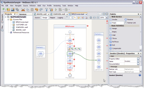
 To Edit the Web Service : Reply1
-
Click Web Service : Reply1. Click Edit.
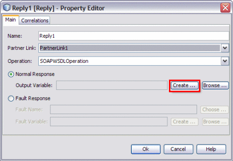
This opens the Reply1 [Reply] - Property Editor.
-
Select the properties from the Main tab. Select PartnerLink1 from the drop-down list.
The IDE fills in the Operation field with SOAPWSDLOperation.
-
Follow the steps to create a New Output Variable.
-
Make sure to select the Normal Response radio button.
-
Click the Create button next to the Output Variable field.
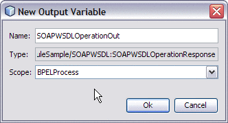
This opens the New Output Variable dialog box.
-
Change the value in the Name field. This is optional.
Reply1 is displayed, by default.
-
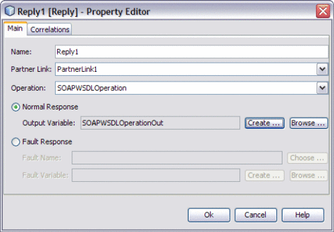
Click OK.
-
-
Click OK to close the Reply1 [Reply] - Property Editor.
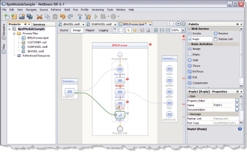
 To Edit the Basic Activities : Assign1
-
Double-click the Basic Activity : Assign1.
This displays the BPEL Mapper window.
-
Expand the node in the Source tree pane (the left pane) of the BPEL Mapper under Output —> Variables.
For example, SOAPWSDLOperationIn
A part1 node appears under the SOAPWSDLOperationIn node.
-
Expand the node in the Destination tree pane (the right pane) of the BPEL Mapper under Input —> Variables.
For example, FindIn
A part node appears under the FindIn node.
-
Select the node in the Source tree pane.
For example, SOAPWSDLOperationIn — part1 — CUSTOMER_Record
-
Drag the selection and map it to the node in the Destination tree pane.
For example, FindIn — part — CUSTOMER_Record
For example, Map the following Variables:
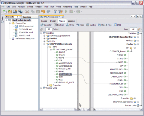
-
Click the Design tab.
Note –A red icon marked against Basic Activities — Assign1 is not shown.
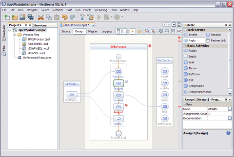
 To Edit the Basic Activities : Assign2
-
Double-click the Basic Activity : Assign2.
This displays the BPEL Mapper window.
-
Expand the node in the Source tree pane (the left pane) of the BPEL Mapper under Output — Variables.
For example, FindOut
-
Expand the node in the Destination tree pane (the right pane) of the BPEL Mapper under Input — Variables.
For example, SOAPWSDLOpertionOut
-
Select the node in the Source tree pane.
For example, FindOut : part : CUSTOMER_Record
-
Drag the selection to the node in the Destination tree pane.
For example, SOAPWSDLOpertionOut : part1 : CUSTOMER_Record
For example, Map the following variables:
-
PHONE : PHONE
-
STATE : STATE
-
NAME : NAME
-
ZIP : ZIP
-
ADDRESSLINE1 — ADDRESSLINE1
-
ADDRESSLINE2 — ADDRESSLINE2
-
CREDIT_LIMIT — CREDIT_LIMIT
-
EMAIL — EMAIL
-
CUSTOMER_ID — CUSTOMER_ID
-
CITY — CITY
-
FAX — FAX
-
DISCOUNT_CODE — DISCOUNT_CODE
Finally, map part : part1.
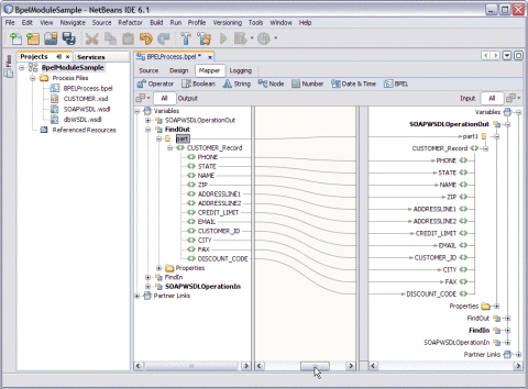
-
-
Click the Design tab.
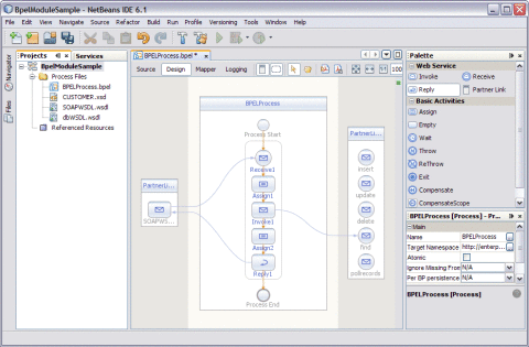
The final output is as shown in the illustration.
-
Right-click the project node and select Clean and Build.
For example, BpelModuleSample
The following message is displayed.
BUILD SUCCESSFUL (total time: 2 seconds).
-
Click Save All.
Validating BPEL
The BPEL Designer has a built-in BPEL code validation functionality that helps create well-formed, valid and standard-compliant code. The code is checked for errors and is notified if validation fails.
 To Invoke Explicit Validation
To invoke explicit validation, perform any one of the following:
-
Right-click the source to invoke the pop-up menu in the Source view and choose Validate XML (Alt-Shift-F9).
-
Click the Validate XML button (Alt-Shift-F9) on the Editor toolbar in the Design view.
Design View : Notifications
The user is notified about validation errors or success in the Output window, in the Design view, and in the Navigator.
The Design View
The Design view shows the results of both real-time and explicit validation in callout windows on the diagram and the error stripe.
In the illustration,
Note –
A red cross next to an element on the diagram means that the element has not passed validation and the output contains errors.
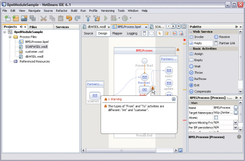
A yellow triangle with an exclamation mark means that the element has not passed validation and the output contains warnings.
A red cross in the Design view means there are both errors and warnings.
If you click the cross or the triangle, a callout window appears with a list of errors and/or warnings.
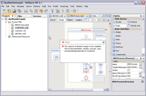
The callout window includes messages related to validation in accordance with all the criteria listed above. Messages related to the real-time validation are constantly updated.
In the Design view, validation results are also shown by the error stripe, which is a strip to the right of the scroll bar that contains red marks if some elements have not passed validation. The error stripe represents the entire diagram, not just the portion that is currently displayed. You can immediately see if the BPEL process contains errors without having to scroll through the entire diagram. You can click a red mark to jump to the element that causes problems. If no errors are detected, the small square in the error stripe is green.
Creating the Composite Application Project
Add the JBI module to the BPEL Module project before deploying the Composite Application. Deploying the project makes the service assembly available to the application server, thus allowing its service units to run.
 To Create the Composite Application Project
-
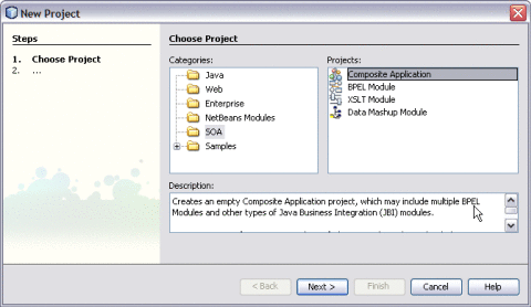
Choose File —> New Project from the main menu.
This opens the New Project wizard.
-
Select the SOA node from the Categories list.
-
Select the Composite Application node from the Projects list.
-
Click Next.
-
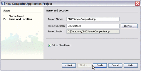
Type the Project Name in the Project Name field.
For example, DBBCSampleCompositeApp
-
Click Finish.
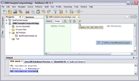
The Projects window now contains a project node for a Composite Application project called DBBCSampleCompositeApp.
-
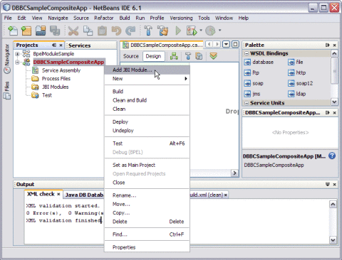
Right-click either the Composite Application Project node or expand the node and select JBI Modules.
For example, DBBCSampleCompositeApp
-
Select Add JBI Module.
-
Select the Project. Click Add Project JAR Files.
For example, BpelModuleSample
The Project JAR Files is build/SEDeployment.jar.
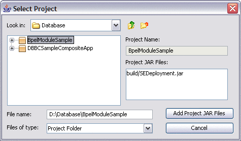
The BpelModuleSample.jar file is added into the project.
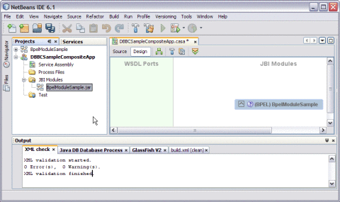
-
Click Save All.
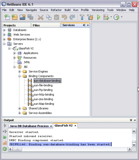
A detailed illustration is as shown on the deployed JBI Components.
-
Expand IDE, open the Services window, expand the GlassFish V2 node, and expand the JBI node.
-
Right-click sun-database-binding and click Start.
Note –If you do not see the JBI node, you need to start the Application Server by choosing Start from the pop-up menu of the GlassFish V2 node.
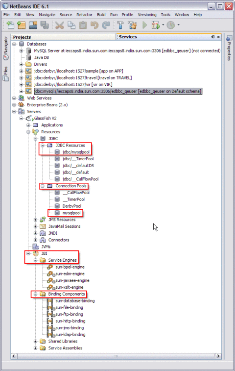
-
-
Right-click the Composite Application project node and select Clean and Build.
For example, DBBCSampleCompositeApp
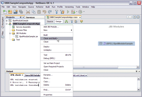
The CASA Editor displays the build of DBBCSampleCompositeApp.
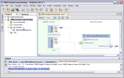
A message is displayed in the Output window:
BUILD SUCCESSFUL (total time: 2 seconds)
-
Click Save All.
Deploying and Testing the Composite Application
In this section, you deploy the Composite Application project and then test the deployed application. Start the Sun Java System Application Server before deploying the project. See Starting the GlassFish V2 Application Server.
 To Deploy the Composite Application
Before You Begin
Troubleshooting
-
Stop the GlassFish V2 Application Server and Restart to ensure the connection.
-
Logout of the Sun Java System Application Server Admin Console and Login.
-
Go to Resources —> JDBC —> Connection Pools —> Choose the defined Connection Pool.
For example, mysqlpool
-
Click the Connection Pool.
The Edit Connection Pool screen is displayed.
-
Ping the Connection Pool.
The following confirmation message box is displayed.
Ping Successful

-
Select the project node in the Projects window.
For example, DBBCSampleCompositeApp
-
Right-click and choose Deploy.
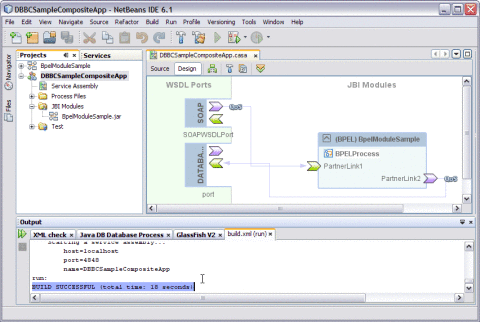
After successful deployment of the project the following message appears in the Output window:
BUILD SUCCESSFUL (total time: 18 seconds)
 To Test the Composite Application
-
Click Test.
-
Right-click and select New Test Case.
-
Enter the Test Case Name.
For example, DBBCTestCase
-
Click Next.
-
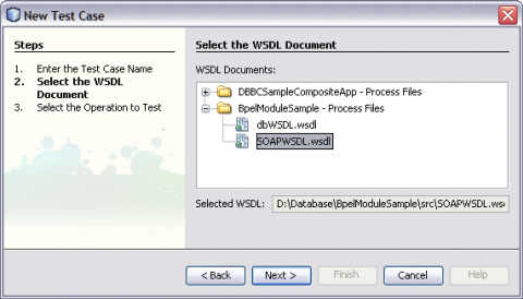
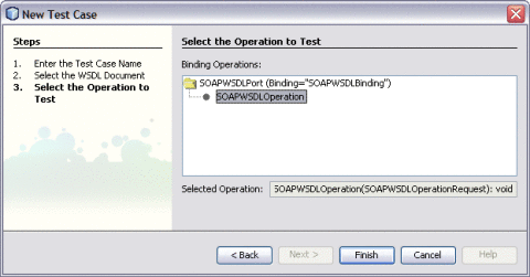
Select the WSDL Document.
-
Click Finish.
The Source Code is as shown.
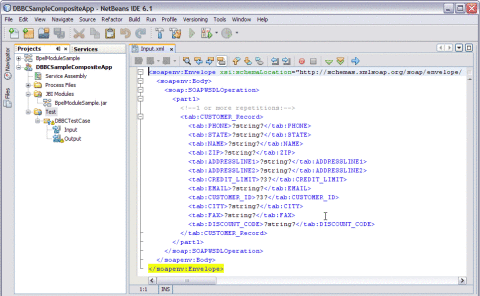
-
Enter the string values.
For example,
-
NAME — Nano Apple
-
CUSTOMER_ID — 3
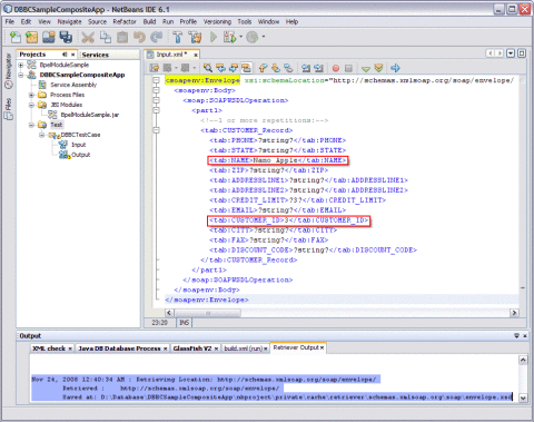
When you enter the string values in the Input.xml window, the output console displays Retrieve.xml. This window displays the location to save the data.
-
-
Right-click the Test Case and click Run.
For example, DBBCTestCase
A confirmation box to overwrite the Output is displayed. Click Yes to overwrite.

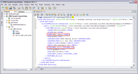
The Output is as shown in the illustration.
Debug the Test Case
You can debug the test case.
 To Debug the Test Case
-
Right-click on the Test Case and select Debug.
For example, DBBCTestCase1
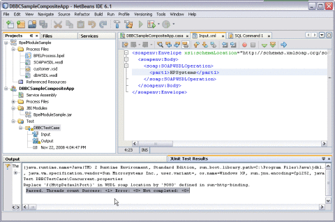
A message is displayed as shown in the illustration.
For a demo, see http://wiki.open-esb.java.net/Wiki.jsp?page=DatabaseBindingComponentFlightDetails.
Creating a BPEL Module Process Using Prepared Statements
A Prepared Statement represents a SQL statement that has been compiled. Prepared statements can be used to perform insert, update, delete and query operations.
Prepared statements provide the ability to create queries that are more secure, have better performance, and are more convenient to write. They come in two flavors: bound parameter prepared statements, and bound result prepared statements.
Prepared statements allow query templates to be created and then stored on the database server. When a query needs to be made, data to fill in the template is sent to the database server, and a complete query is formed and then executed.
The basic process for creating and using bound parameter prepared statements is simple.
A query template is created and sent to the database server. The database server receives the query template, validates it to ensure that it is well-formed, parses it to ensure that it is meaningful, and stores it in a special buffer. It then returns a special handle that can later be used to reference the prepared statement. When a query needs to be made, data to fill in the template is sent to the database server, and then a complete query is formed and then executed.
This process has some very important behaviors wrapped up in it.
The body of the query is only sent to the database server once. On requests to execute the query, only the data to fill in the template needs to be delivered to the database server. Most of the work required to validate and parse the query only needs to be done a single time, instead of each time that the query is executed. Additionally, for queries that contain a small amount of data, the overhead of sending the query is greatly reduced.
For steps, see the following links:
-
Creating a WSDL Document For Type : DATABASE
-
Select Type — Prepared Statement.
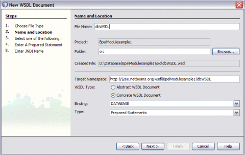
-
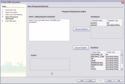
Enter a valid Prepared Statement.
-
Click Discover Parameters to view types for the parameters.
-
Click Discover Resultset to discover the Resultset types.
-
Click Next.
-
Enter JNDI Name.
-
Click Finish.
-
For a demo, see http://wiki.open-esb.java.net/Wiki.jsp?page=DatabaseBindingComponentPollScenario.
Creating a BPEL Module Project Using Procedures
A Procedure represents a database stored procedure. Fields correspond to the arguments of a stored procedure while methods are the operations that you can apply. It allows you to execute a stored procedure.
Note –
Select a Procedure from the list and add the stored procedure to the Selected Stored Procedures console.
-
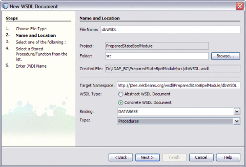
Creating a WSDL Document For Type : DATABASE
-
Select Type — Procedures
-
Click Next.
-
Select the URL from the drop-down list.
-
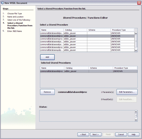
Select a Stored Procedure and click Add to move the selected Stored Procedure to the Selected Stored Procedure panel.
-
Click Next.
-
Enter JNDI Name.
-
Click Finish.
-
For procedure, see the following links:
For a demo, see http://wiki.open-esb.java.net/Wiki.jsp?page=DatabaseComponentStoredProcedure.
Creating a BPEL Module Project Using SQL File
This is the script that contains the data definition statements for the MySQL database. The file filter for the file open dialog window defaults to *.sql so you should only be able to view files with the .sql extension.
For procedure, see the following links:
-
Creating a WSDL Document For Type : DATABASE.
-
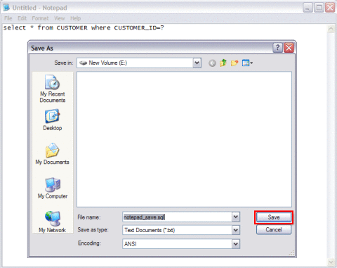
Create a .sql file using Notepad.
-
Save the file in a folder location.
-
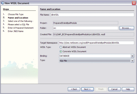
Choose Type — SQL File.
-
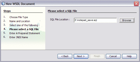
Click Browse to select the saved .sql file.
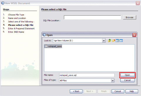
The selected file is displayed as shown in the Figure.
-
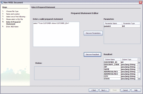
Click Discover Parameters to view types for the parameters.
-
Click Discover Resultset to discover the Resultset types.
-
Click Next.
-
Enter JNDI Name.
-
Click Finish.
-
For a demo, see http://wiki.open-esb.java.net/Wiki.jsp?page=BuildSampleProjectSQLFileDatabaseWSDL.
- © 2010, Oracle Corporation and/or its affiliates

