JavaScript is required to for searching.
Skip Navigation Links
Exit Print View
Sun Blade 6000 Ethernet Switched NEM 24p 10GbE

User’s Guide

search filter icon
search icon

Document Information

Using This Documentation

Related Documentation

CLI Command Modes

Feedback

Support and Accessibility

Understanding the Switched NEM

Switched NEM Features Overview

Switched NEM External Ports

Switched NEM Internal Ports

Switched NEM LEDs

Installing or Replacing the Switched NEM

Install the Switched NEM

Verifying the Switched NEM Installation

Verify Installation With the CMM ILOM Web Interface

Verify Installation With the CMM ILOM CLI

Finish the Switched NEM Installation

Install the Fabric Expansion Module in the Server Blade

Installing or Removing SFP+ or QSFP Optical Transceiver Modules

Install an SFP+ or QSFP Optical Transceiver Module

Remove an SFP+ or QFSP Optical Transceiver Module

SFP+ Cabling Guidelines

QSFP Cabling Guidelines

Remove a Switched NEM

Replace a Switched NEM

Managing the NEM Remotely (ILOM)

ILOM Overview

ILOM Documentation

ILOM Product Updates

ILOM Features Not Supported

Connecting to ILOM

ILOM Connection Options

Configuring an Externally Accessible IP Address on the NEM

Connecting to the NEM ILOM

Connecting to the NEM ILOM Through the CMM ILOM

Connecting With SEFOS

SEFOS Overview

Connect to SEFOS

Configure SEFOS User Privileges

Special Considerations for RADIUS Users

Configure User Privileges for RADIUS Users

Backing Up and Restoring the ILOM and SEFOS Configuration

Understanding Sensors and Indicators

Presence Sensors

Switched NEM Indicators

Fan Threshold Sensors

Temperature Sensors

Voltage Sensors

Glossary

Index

Switched NEM LEDs

This figure shows the Switched NEM LEDs, viewed from the back of the chassis. The table describes the LED behavior.

Figure 2 Switched NEM LEDs and Buttons
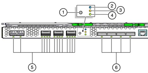
image:Graphic showing the Switched NEM.

Table 3 Switched NEM LED Descriptions

LED/Button Name
Description
1
Locate button and LED (white)
Helps locate each Switched NEM.
  • Push and release to make the Locate LED blink.

  • If the LED is blinking, push and release this button to stop the blinking.

  • Push and hold down the button for 5 seconds to initiate a “push-to-test” mode. This mode illuminates LEDs 1 through 4 for 15 seconds. The LED can be enabled remotely.

2
OK to Remove LED (blue)
Not used at this time. The Switched NEM can be removed from a powered-on system without referring to this LED.
3
Module Fault LED (amber)
Has two states:
  • Off: No fault.

  • On: An event has been acknowledged, and service action is required.

4
Module Activity (Power/OK) LED (green)
Has two states:
  • Off: Module is powered off.

  • On: Module is powered on.

5
Ethernet Link Status/Activity for 10GbE connection (green)
Has three states:
  • Off: No link or activity on the SFP+ or QSFP port.

  • On: A link has been established on the SFP+ or QSFP port.

  • Blinking: There is activity on the SFP+ or QSFP port.

6
SAS Link/Activity (green)
Not supported at this time.
Related Information