Front Indicator Module
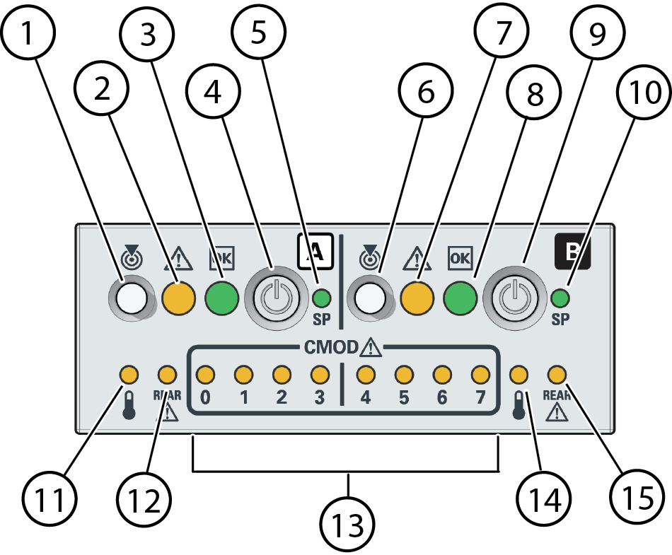
The following figure shows the controls and indicators on the front indicator
module (FIM).

|
|
|
|
1
|
System A
|
Locate Button and indicator
|
|
2
|
System A
|
Fault-Service Required indicator
|
|
3
|
System A
|
System OK indicator
|
|
4
|
System A
|
On/Standby button
|
|
5
|
System A
|
SP OK indicator
|
|
6
|
System B
|
System Locate Button and Indicator
|
|
7
|
System B
|
Fault-Service Required indicator
|
|
8
|
System B
|
System OK indicator
|
|
9
|
System B
|
On/Standby button
|
|
10
|
System B
|
SP OK indicator
|
|
11
|
System A
|
System Overtemperature Warning indicator
|
|
12
|
System A
|
Chassis rear Fault-Service Required indicator
|
|
13
|
0 through 3 - System A
4 through 7 - System B
|
CMOD Fault-Service Required indicators 0 - 8 (from left to
right)
|
|
14
|
System B
|
System Overtemperature Warning indicator
|
|
15
|
System B
|
Chassis rear Fault-Service Required indicator
|
|
Note -
SMOD 1 is inactive on single 4-socket systems and has reduced
functionality on single 8-socket systems.
