Back Panel Connectors and Ports
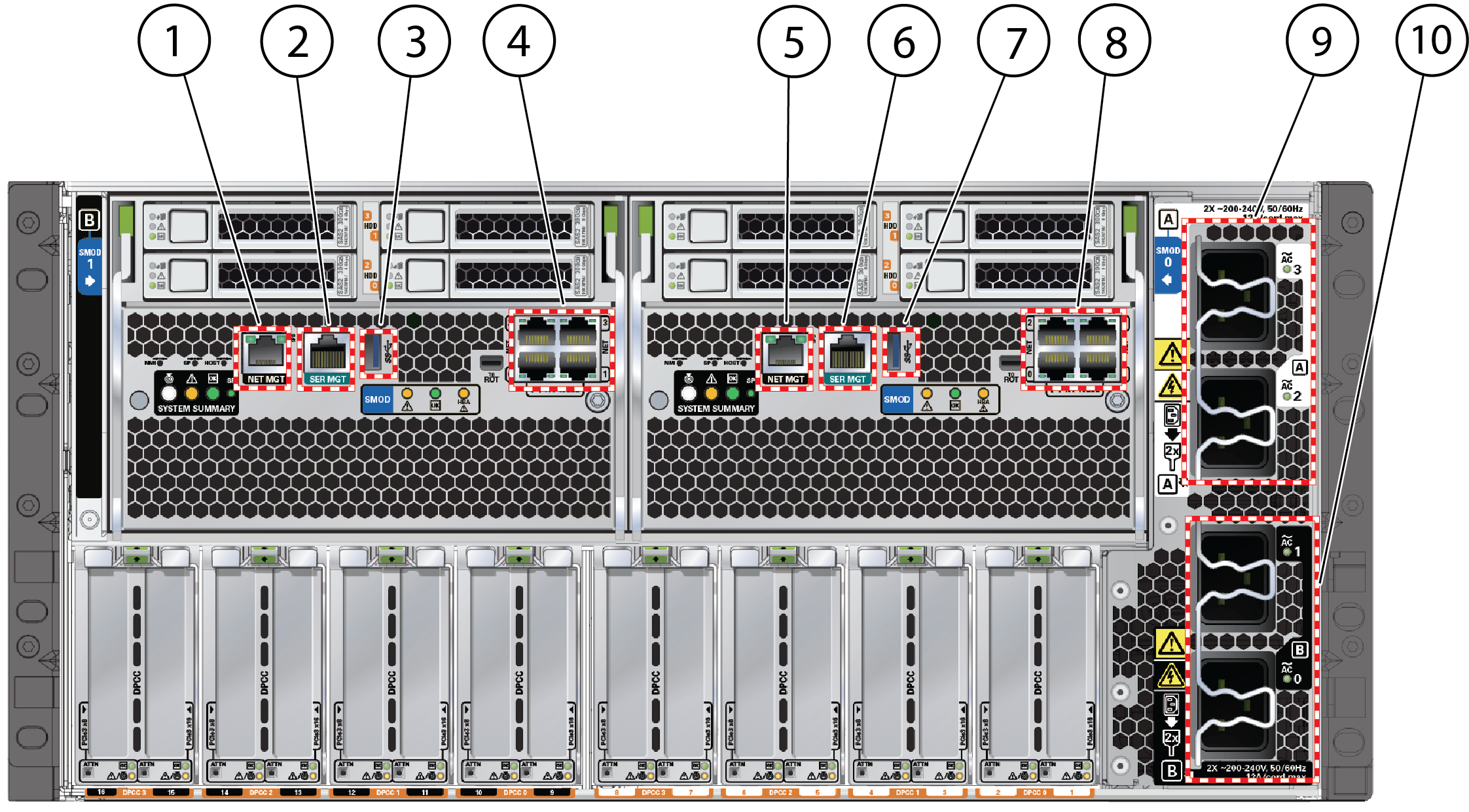
The following figure shows the locations of the server back panel connectors and
ports.

|
|
|
|
|
1
|
Net management port (NET MGT)
|
System B –SMOD1
|
Dual 4-port systems only
|
|
2
|
Serial management port (SER MGT)
|
System B –SMOD1
|
Dual 4-port systems only
|
|
3
|
USB port
|
System A or B
|
-
Inactive on single 4-port systems
-
System B on dual 4-port systems
-
System A on single 8-port systems
Dual 4-port systems only
|
|
4
|
-
NET0, NET1, NET2, and NET3 ports on dual 4-port and single
8-port systems
-
Unused on single 4-port systems
|
System B –SMOD1
|
Dual 4-port and single 8-port systems
|
|
5
|
Net management port (NET MGT)
|
System A – SMOD0
|
All systems
|
|
6
|
Serial management port (SER MGT)
|
System A – SMOD0
|
All systems
|
|
7
|
USB port
|
System A – SMOD0
|
All systems
|
|
8
|
NET0, NET1, NET2, and NET3 ports on all systems
|
System A – SMOD0
|
All systems
|
|
9
|
Power connectors 2 and 3. Connect to 200-240 VAC only.
|
System A – SMOD0
|
Always connect all four power supplies
|
|
10
|
Power connectors 0 and 1. Connect to 200-240 VAC only.
|
System B –SMOD1
|
Always connect all four power supplies
|
|

