Go to main content

Oracle® Server X7-8 Installation Guide

Exit Print View

Updated: April 2018


Back Panel Components

The components on the back panel are divided between System A and System B. System A is associated with SMOD0. System B is associated with SMOD1.

  • In single 4-socket systems, System A is active and System B is inactive.

  • In dual 4-socket systems, System A and System B are active and act as independent servers.

  • In single 8-sockets, System A and System B are active and merged into a single server, although some redundant features in SMOD1 are nonfunctional.

The following figure shows the Oracle Server X7-8 back panel.
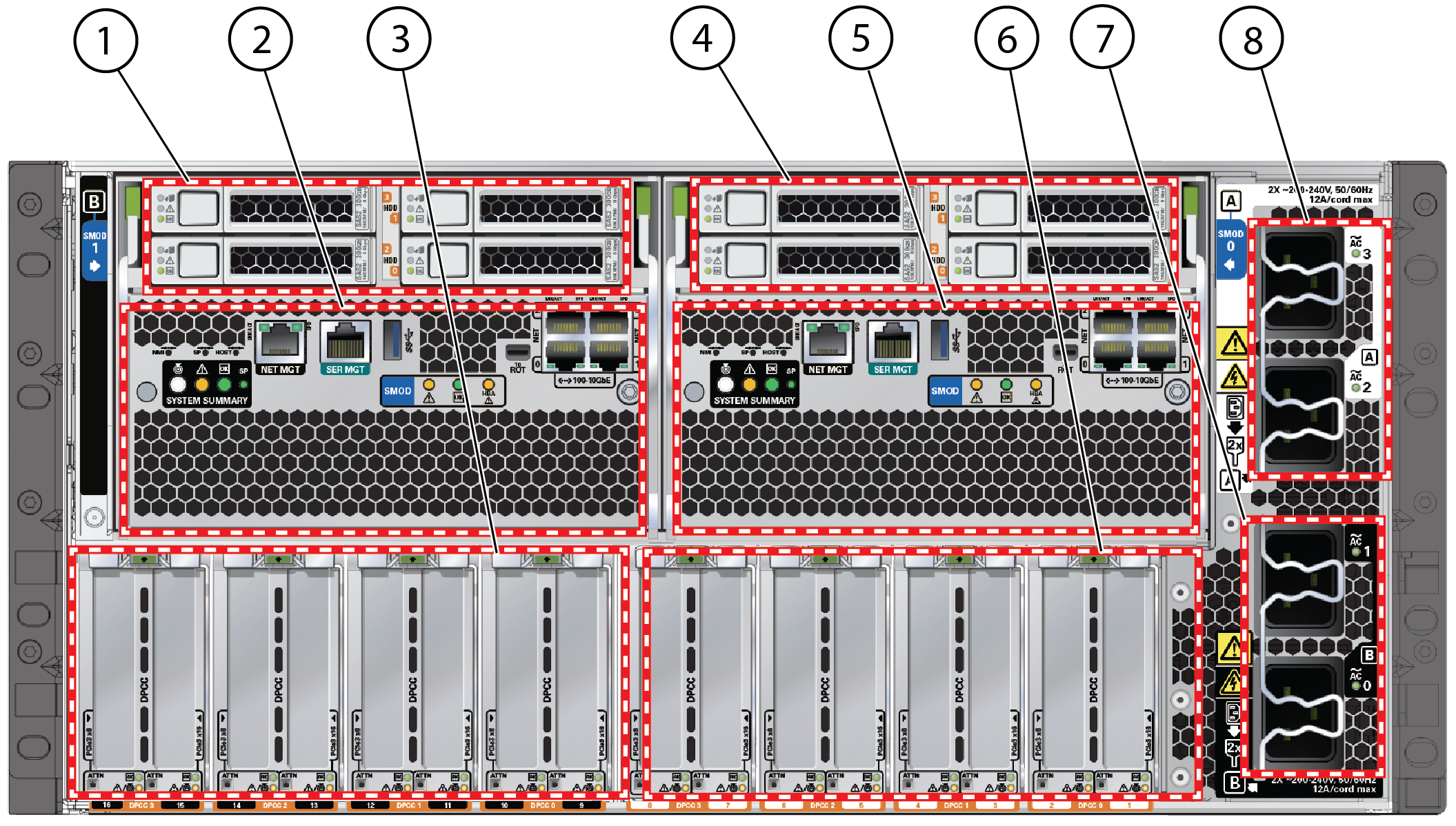
image:Picture of system back panel with callouts.
Callout
Assignment
Description
1
System B
HDD/SSD slots:
  • Top row: 3, 1

  • Bottom row: 2, 0

2
System B
SMOD1
3
System B
PCIe cards 9 through 16
  • PCIe 16 is on the left

  • PCIe 9 is on the right, middle

4
System A
HDD/SSD slots 0 through 3:
  • Top row: 3, 1

  • Bottom row: 2, 0

5
System A
SMOD0
6
System A
PCIe cards 1 through 8
  • PCIe 8 is on the middle left

  • PCIe 1 is on the right

7
System A
AC inputs 2 and 3
8
System B
AC inputs 0 and 1

For information on how to interpret the status indicators (LEDs), refer to the Troubleshooting and Diagnostics in Oracle Server X7-8 Service Manual.

Back Panel Status Indicators and Buttons

The following figure shows the indicators, buttons, and ports on an SMOD.

  • For single 4-socket systems, the indicators on SMOD1 are inactive.

  • For single 8-socket systems, the SMOD1 indicators are still active but the system-level indicators remain inactive.
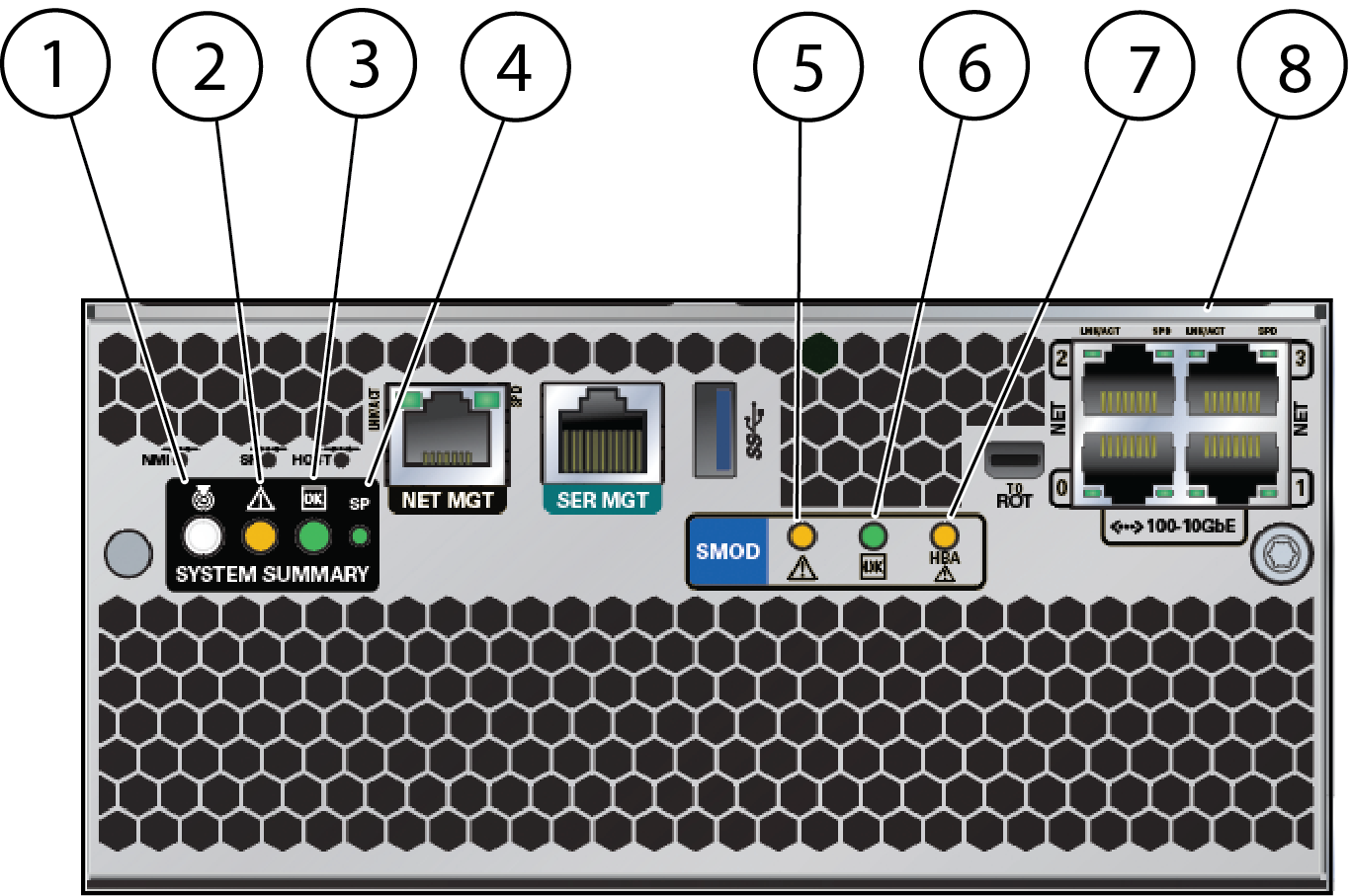
image:Closeup of indicators on SMOD.
Callout
Description
1
Locate indicator/button – Used to identify the server.
2
Chassis Service Required indicator (SMOD0 only) – For details, refer to Oracle Server X7-8 Service Manual.
3
System OK – For details, see Controlling System Power.
4
SP OK – Steady on if SP is operating, flashes while SP is booting, off if SP has no power.
5
SMOD Service Required indicator – Indicates a system module (SMOD) fault
6
SMOD OK indicator – Steady on if SMOD is operating, flashes while SMOD is booting, off if SMOD has no power.
7
HBA Service Required indicator – Indicates a host bus adapter (HBA) fault
8
NET0, NET1, NET2, and NET3 ports

Note -  For details on system power and the related controls and indicators, see Controlling System Power.

Storage Controls and Indicators

The following figure shows the storage controls and indicators.

image:Figure of front of HDD or SSD with callouts.
Callout
Description
1
OK indicator
2
Service Required (fault) indicator
3
Ready to Remove indicator
4
Storage drive release button
5
Storage drive lever
6
Drive type and capacity labels