Power On the SPARC SuperCluster T4-4
- Ensure that each of the main power cords is connected.
- Turn on the facilities circuit breakers.
-
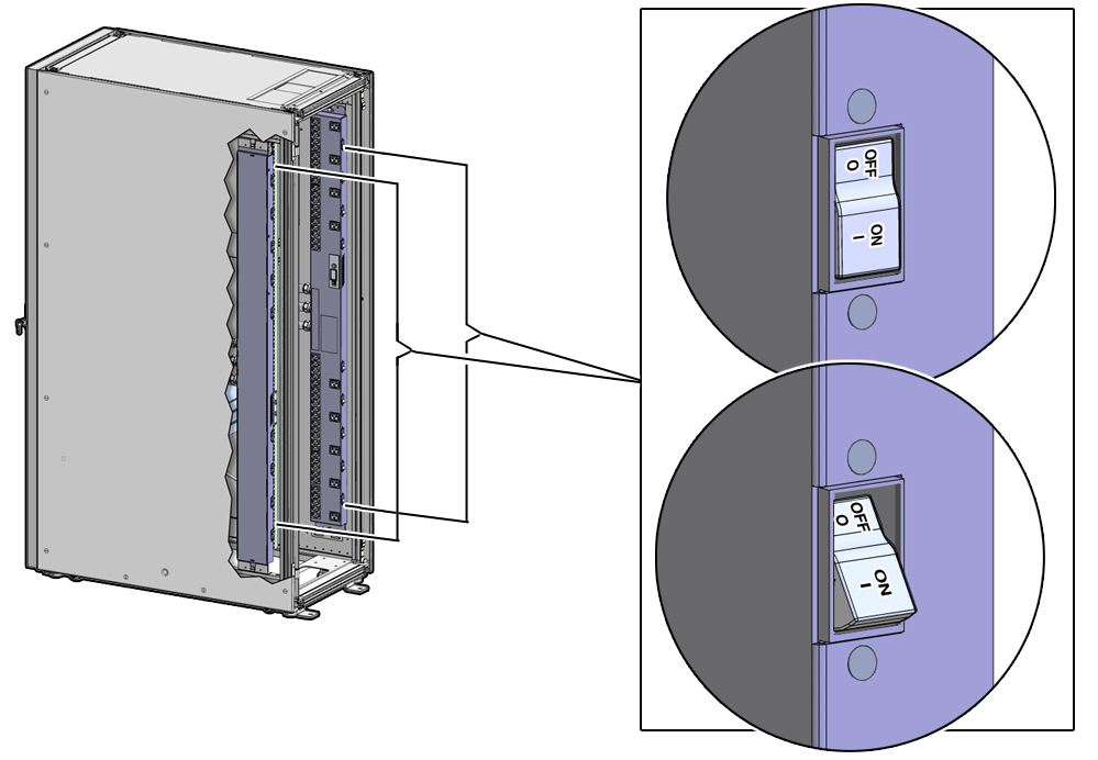
Switch on power distribution unit B (PDU B) only.
Note - Do not turn on PDU A at this time.PDU B is located on the right side of the rear of the rack. See below.
Press the ON (|) side of the toggle switches on PDU B.

Powering on PDU B will power on only half of the power supplies in the rack. The remaining power supplies will be powered on in Step 4.
The LEDs for the components should be in the following states when all of the PDU B circuit breakers have been turned on:
-
Check the SPARC T4-4 servers:
-
Power OK green LED – Blinking
-
Service Action Required amber LED – Off
-
PS1 and PS3 Power LEDs – Green
-
PS0 and PS2 Power LEDs – Amber
If the LEDs are not in these states, press the Power buttons at the fronts of the SPARC T4-4 servers.
-
-
Check the Sun ZFS Storage 7320 storage controllers:
-
Power OK green LED (front panel) – Blinking while the operating system is booting up.
The Power OK LED changes to Steady On after the operating system has booted up (this could take up to 10 minutes)
-
Service Action Required amber LED (front panel) – Off
-
Left power supply (rear panel) – Green
-
Right power supply (rear panel) – Off
If the LEDs are not in these states, press the Power buttons at the fronts of the Sun ZFS Storage 7320 storage controllers.
-
-
At the rear of the Sun Disk Shelf, press both Power buttons to the
On positions.
The LEDs should be:
-
Service Action Required amber LED – Off
-
Left power supply (rear panel) – Amber
-
Right power supply (rear panel) – Green
-
-
Check the fronts of the Sun Datacenter InfiniBand Switch 36 switches:
-
Left power supply LED (PS0 LED) – Red
-
Right power supply LED (PS1 LED) – Green
-
-
Check the front of the Cisco Catalyst 4948 Ethernet management
switch:
-
PS1 LED – Red
-
PS2 LED – Green
-
-
Check the SPARC T4-4 servers:
-
Switch on power distribution unit A (PDU A).
PDU A is located on the left side of the rack.
Press the ON (|) side of the toggle switches on PDU A.

The LEDs for the components should be in the following states when all of the PDU A circuit breakers have been turned on.
-
Check the SPARC T4-4 servers:
-
Power OK green LED – Blinking
-
Service Action Required amber LED – Off
-
PS1 and PS3 Power LEDs – Green
-
PS0 and PS2 Power LEDs – Green
-
-
Check the Sun ZFS Storage 7320 storage controllers:
-
Power OK green LED – On
-
Service Action Required amber LED – Off
-
Left power supply – Green
-
Right power supply – Green
Tip - You can ping the IP address assigned to the Sun ZFS Storage 7320 storage controller to verify whether the system is up and running. For the default NET0 IP addresses, see Default IP Addresses. Alternatively, you can try to launch the administration console for the storage appliance. Before you can ping the IP address or launch the administration console, you must connect a laptop to the rack, as described in Connect a Laptop to the SPARC SuperCluster T4-4. -
-
Check the Sun Disk Shelf:
-
Service Action Required amber LED – Off
-
Left power supply – Green
-
Right power supply – Green
-
-
Check the Exadata Storage Server:
-
Power OK LED – Off while Oracle ILOM is booting (about 3 minutes), then blinking
-
Service Action Required amber LED – Off
-
-
Check the fronts of the Sun Datacenter InfiniBand Switch 36 switches:
-
Left power supply LED (PS0 LED) – Green
-
Right power supply LED (PS1 LED) – Green
-
-
Check the front of the Cisco Catalyst 4948 Ethernet management
switch:
-
PS1 LED – Green
-
PS2 LED – Green
-
-
Check the SPARC T4-4 servers: