Reference Drawings
The InfiniBand (IB) fabric connects together the IB switches and the servers listed below in the SPARC SuperCluster T4-4. For IB cable information, see InfiniBand Fabric .
The Ethernet Management Switch also connects to the servers listed below. For 1 Gb/s Cat 5E cabling information, see Ethernet Management Switch.
The following figures are in this section:
-
Sun Datacenter InfiniBand Switch 36, Figure 12
-
IB Spine Switch (slot U1)
-
IB Leaf Switch No. 1 (slot U18)
-
IB Leaf Switch No. 2 (slot U24)
-
-
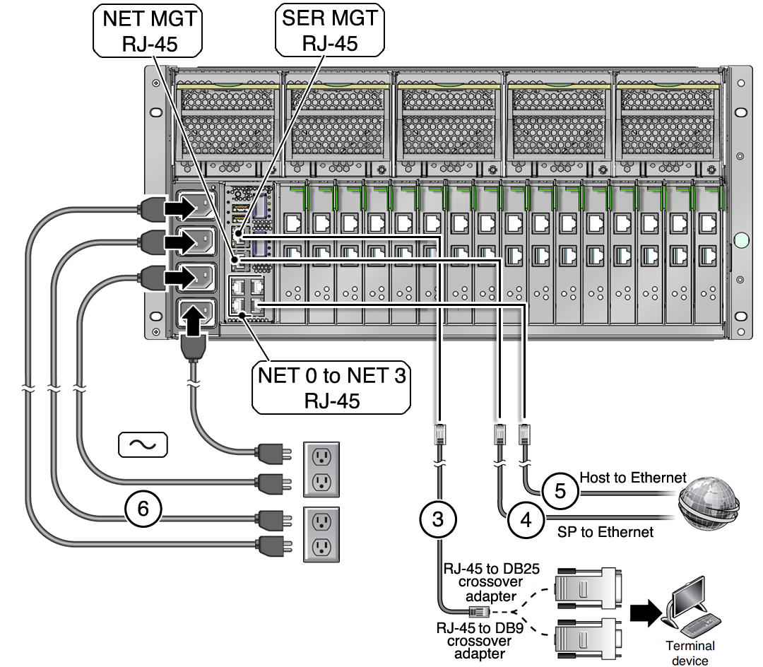
SPARC T4‐4 servers, Figure 13
-
SPARC T4-4 No. 1 (slot 8)
-
SPARC T4-4 No. 2 (slot 13)
-
SPARC T4-4 No. 3 (slot 27) (full rack only)
-
SPARC T4-4 No. 4 (slot 32) (full rack only)
-
-
Sun ZFS Storage 7320 storage controllers, Figure 14
-
Sun ZFS Storage 7320 storage controller No. 1 (slot 25)
-
Sun ZFS Storage 7320 storage controller No. 2 (slot 26)
-
-
Exadata Storage Servers, Figure 15
-
Exadata Storage Server No. 1 (slot 2)
-
Exadata Storage Server No. 2 (slot 4)
-
Exadata Storage Server No. 3 (slot 6)
-
Exadata Storage Server No. 4 (slot 37) (full rack only)
-
Exadata Storage Server No. 5 (slot 39) (full rack only)
-
Exadata Storage Server No. 6 (slot 41) (full rack only)
-
-
The Ethernet Management Switch, Figure 16
-
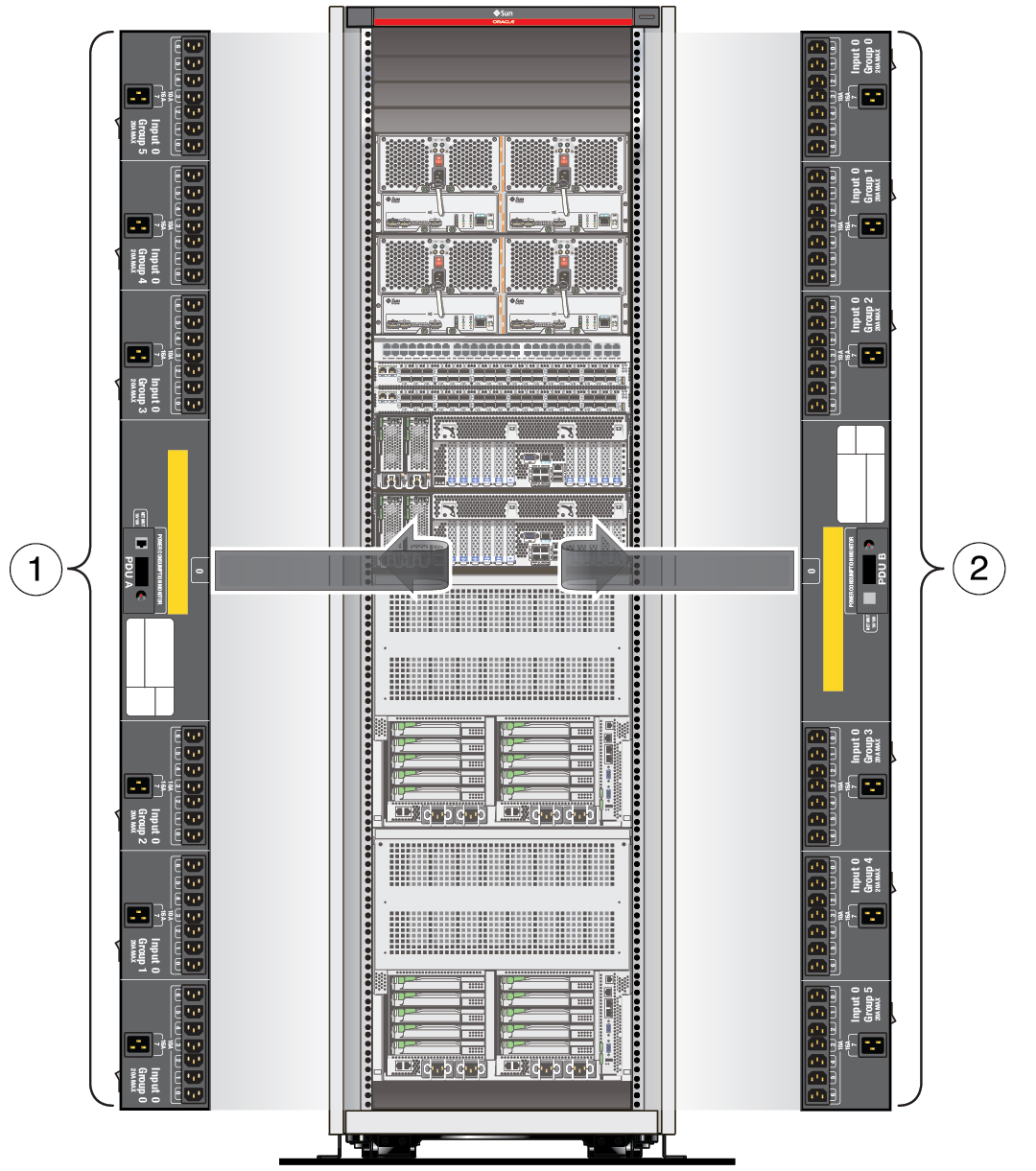
PDU circuit breakers and AC sockets, Figure 17
Figure 12 Sun Datacenter InfiniBand Switch 36

Figure Legend
1 NET MGT 0 and NET MGT 1 ports
2 InfiniBand ports 0A-17A (upper ports)
3 InfiniBand ports 0B-17B (lower ports)
Figure 13 SPARC T4-4 Server

Figure Legend
1 NET MGT, network management port
2 SER MGT, serial management port
3 RJ-45 cable from SER MGT port to a terminal device, might require an adapter
4 RJ-45 cable, connects the SPARC T4-4 service processor to the Ethernet
5 RJ-45 cables, connect network ports NET 0-3 to the Ethernet
6 Power cords
Figure 14 Sun ZFS Storage 7320 Storage Controller

Figure Legend
1 Power supply 1
2 Power supply 2
3 System status LEDs
4 Serial management port
5 Service processor network management port
6 Gigabit Ethernet ports NET 0, 1, 2, 3
7 USB ports 0, 1
8 HD15 video connector
Figure 15 Exadata Storage Server

Figure Legend
1 Power supply 1
2 Power supply 2
3 System status LEDs
4 Serial management port
5 Service processor network management port
6 Gigabit Ethernet ports NET 0, 1, 2, 3
7 USB ports 0, 1
8 HD15 video connector
Figure 16 Ethernet Management Switch (Cisco Catalyst 4948 Ethernet Switch)

Figure Legend
1 Indicators and reset switch
2 Ports 1-16, 10/100/1000BASE-T Ethernet
3 Ports 17-32, 10/100/1000BASE-T Ethernet
4 Ports 33-48, 10/100/1000BASE-T Ethernet
5 CON (upper), MGT (lower)
6 Ports 45-48, 10-Gigabit Ethernet
Figure 17 Circuit Breakers and AC Sockets on the PDU

Figure Legend
1 PDU A
2 PDU B