|
|
|
|
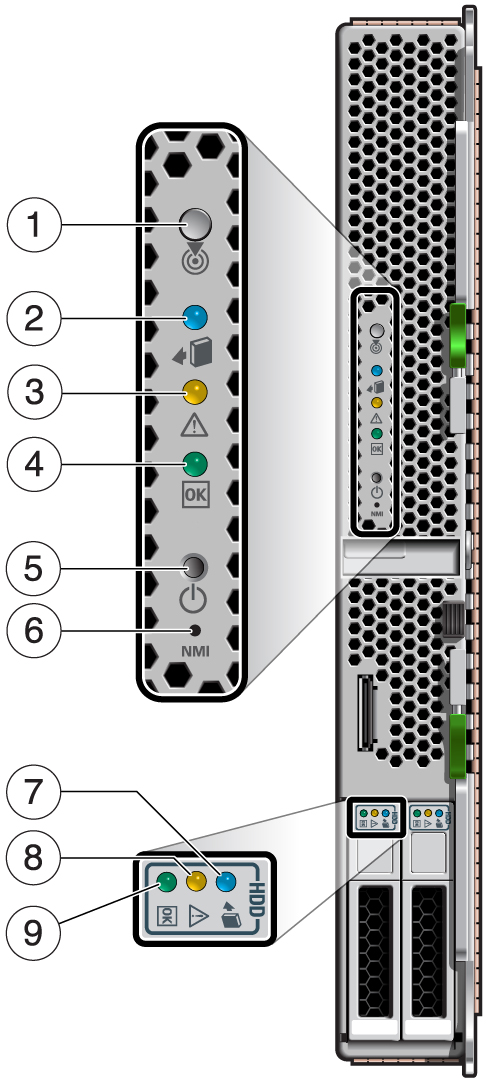
1 |
Locator LED (white) and button |

|
You can turn on the Locator LED to identify
a particular server module. When on, the LED blinks rapidly.
The Locator LED also functions as the Physical Presence switch. |
2 |
Ready to Remove LED (blue) |

|
Indicates whether or not the server module
is safe to remove from the chassis:
|
3 |
Service Action Required LED (amber) |

|
Indicates these conditions:
The fmadm faulty command provides details
about any faults that cause this indicator to light. See Managing Faults. Under some fault conditions, individual component fault LEDs
are turned on in addition to the Service Action Required LED. See Drive LEDs and DIMM FRU Names. |
4 |
Power OK LED (green) |

|
Indicates these conditions:
Off – Host
is not running in its normal state. Host power might be off. The SP
might be running. Steady on – Host
is powered on and is running in its normal operating state. No service
actions are required. Fast blink – Host
is running in standby mode and can be quickly returned to full function. Slow blink – A
normal, but transitory activity is taking place. Slow blinking might
indicate that diagnostics are running, or the host is booting.
|
5 |
On/Standby button |

|
The recessed Power button toggles the
host on or off.
|
|
6
|
Reset button
|
NMI
|
For authorized Oracle service use only.
|
7 |
Drive Ready to Remove LED (blue) |

|
Indicates that the drive can be removed
during a hot-plug operation.
|
8 |
Drive Service Action Required LED (amber) |

|
Indicates that the drive has experienced
a fault condition.
|
9 |
Drive OK/Activity LED (green)
|

|
Indicates this drive status:
|

