Install the Internal HBA Card in PCIe Slot 4
- Unpack the replacement host bus adapter (HBA) card, the super capacitor, the SAS cables, and the super capacitor cable, and retrieve the PCIe riser for slot 3.
-
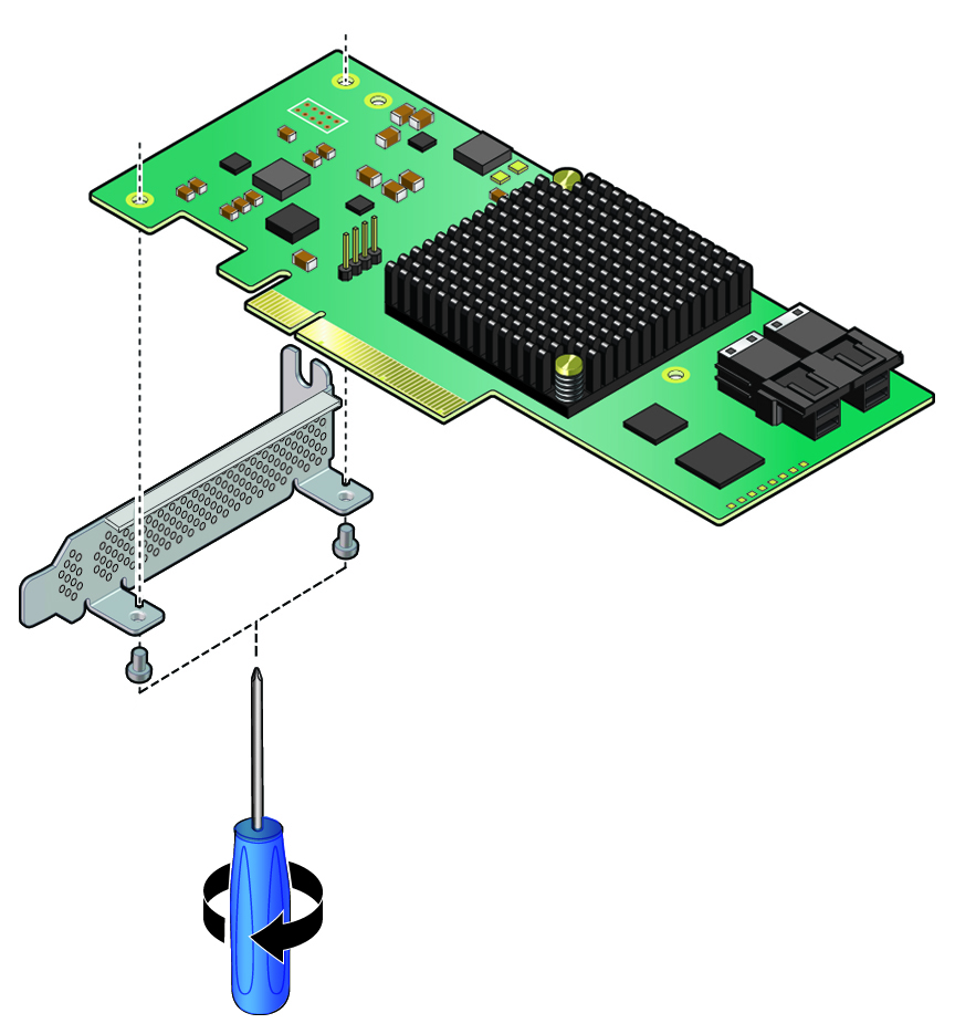
Using a No. 2 Philips screwdriver, remove the standard HBA bracket that
shipped with the replacement HBA card.
-
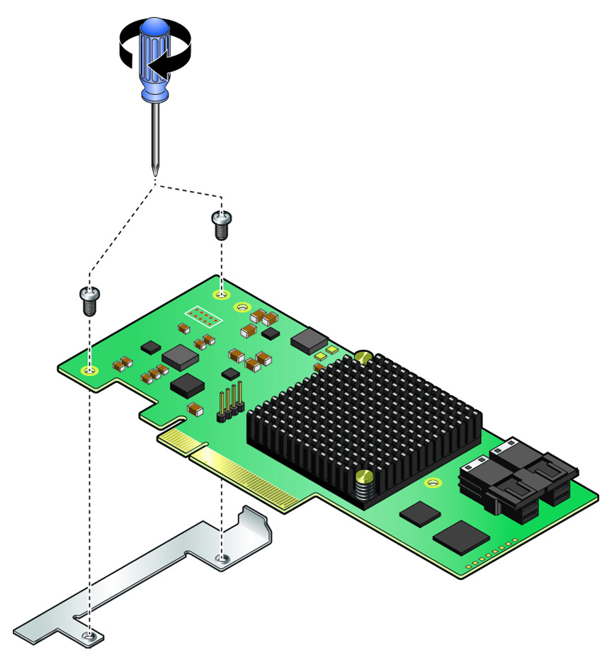
Install the special fitted bracket that was removed in Step 5 in Remove the Internal HBA Card From PCIe Slot 4.
- Carefully guide the SAS cables and super capacitor cable that connect to the disk backplane and the super cable through the chassis mid-wall toward the front of the server.
-
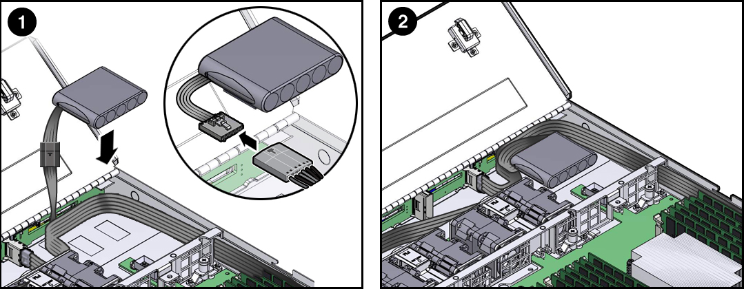
Install the super capacitor into the server.
- Attach the reclosable fasteners supplied with the replacement super capacitor to its underside.
- Connect the super capacitor cable to the super capacitor [1].
- Press the super capacitor into the server's chassis so that it is secured to the existing reclosable fastener [1 and 2].
-
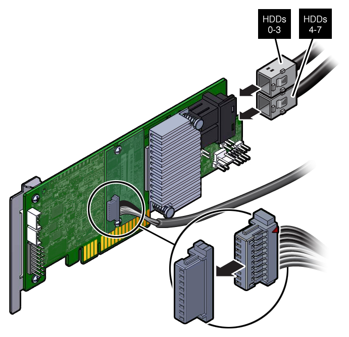
Connect the SAS cables and the super capacitor cable to the internal HBA
card.
-
Insert the rear bracket on the internal HBA card into the rear connector
on the PCIe riser.
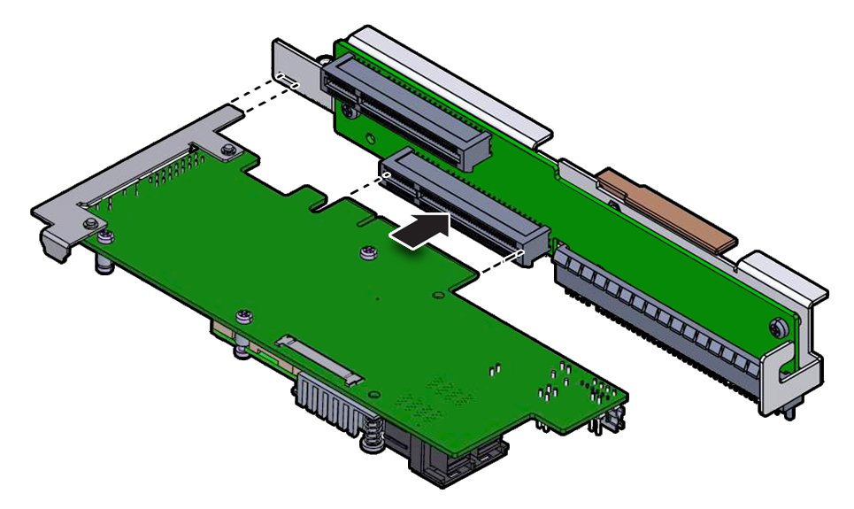
- Insert the internal HBA card connector into the bottom connector on the riser for PCIe slot 3 and 4 .
-
Install the PCIe riser.
For instructions, see Install the PCIe Riser Into PCIe Slots 3 and 4.
-
Install fan module FM0.
See Install a Fan Module.
-
Return the server to operation.
- Close the server fan door.
- Return the server to the normal rack position.
- Reconnect the data cables to the server and reconnect the power cords to the server power supplies.
-
Power on the server.
See Power On the Server.
Verify that the Power/OK status indicator is steady on.