| Skip Navigation Links | |
| Exit Print View | |

|
SPARC M5-32 and SPARC M6-32 Servers Service Manual |
Power System Cage Component Locations
Scalability Card Cage Component Locations
Identifying Internal Components
AC Input Filter and AC Power Cord
RFI Panel, Scalability Assembly, and Midplane Locations
Scalability, DCUs, and PDomains
Cooling Zone Assignments and DCUs
Component Service Task Reference
Oracle ILOM Service-Related Tools
Log In to Oracle ILOM (Service)
Interpreting Log Files and System Messages
View Log Files (Oracle Solaris)
Oracle ILOM Properties That Affect POST Behavior
Front and Rear LED Panel LEDs and Controls
Removing Power From the Server
Prepare to Power Off the Server
Servicing Trim Panels and the Kick Plate
Trim Panel Service Preparation
Service Processor General Status LEDs
Service Processor Network Management Port LEDs
Check a Service Processor Battery
Replace a Service Processor Battery
I/O Switch Board Configuration
Determining Which PDomain Has the I/O Switch Board
Servicing Cable Management Assemblies
Remove a Cable Management Assembly
Install a Cable Management Assembly
Understanding I/O Card Slot Configuration
Identifying I/O Card Slots in an IOU
Understanding I/O Card Slot Device Paths and FRU Paths
I/O Card Slot Device Paths and FRU Paths in Fully-populated DCUs
I/O Card Slot Device Paths and FRU Paths in Half-Populated DCUs
Sun Flash Accelerator F40 PCIe Cards
Locate an I/O Card in the Server
Prepare an I/O Card For Removal
Remove an I/O Card From the Server
Remove an I/O Card From a Carrier
Install an I/O Card in a Carrier
Install an I/O Card in the Server
Remove a Filler Panel From the Server
Remove a Filler Panel From a Carrier
Install a Filler Panel in a Carrier
Install a Filler Panel in the Server
Relocate a Sun Flash Accelerator F40 PCIe Card
Understanding EMS Configurations
EMS and Hard Drive Cage Compatibility
Redundant EMS Control of SAS-Format Drives
Nonredundant EMS Control of SATA-Format Drives
Identifying Hard Drive Slot Locations
EMS Slot Locations in Fully‐Populated DCUs
EMS Slot Locations in Half‐Populated DCUs
Display the Hard Drive Cage Type
Servicing HDDs, SSDs, and Drive Filler Panels
Understanding HDD and SSD Slot Configurations
Redundant and Nonredundant Drive Controllers
Identifying Drive Slot Locations
HDD and SSD Hot-Plug Capabilities
CMU Upgrades in a SPARC M5-32 Server
Display General CMU Information
Display Information for Upgrading CMUs
Servicing the Front Filler Panel
Install the Front Filler Panel
Servicing a Cabled Lower Bus Bar Assembly
Remove a Cabled Lower Bus Bar Assembly
Install a Cabled Lower Bus Bar Assembly
Servicing the Scalability Card Cage
Remove the Scalability Card Cage
Install the Scalability Card Cage
Servicing the Scalability Fans Cable
Remove the Scalability Fans Cable
Install the Scalability Fans Cable
Servicing the Power System Cage
Prepare to Replace Crown Clips on a Bus Bar
Return the Server to Operation
Servicing an I/O Power Cable Assembly
Remove an I/O Power Cable Assembly
Install an I/O Power Cable Assembly
Servicing the Scalability Assembly
Remove the Scalability Assembly
Install the Scalability Assembly
Servicing the Power System Cage to Scalability Assembly Cable
Remove the Power System Cage to Scalability Assembly Cable
Install the Power System Cage to Scalability Assembly Cable
Servicing the PSDB to Scalability Midplane Cable
Remove the PSDB to Scalability Midplane Cable
Install the PSDB to Scalability Midplane Cable
Servicing the Internal Link to Front LED Panel Cable
Remove the Internal Link Cable for the Front LED Panel
Install the Internal Link Cable for the Front LED Panel
Servicing the Rear LED Panel Cable
Remove the Rear LED Panel Cable
Install the Rear LED Panel Cable
Servicing Midplane Power Cables
Prepare to Remove a Midplane Power Cable
Install a Midplane Power Cable
Prepare to Remove the Midplane
Prepare the Old Midplane for Return
Returning the Server to Operation
Note - The IOU replacement kit includes plastic covers to protect the IOU connectors. These covers are to be returned to Oracle.
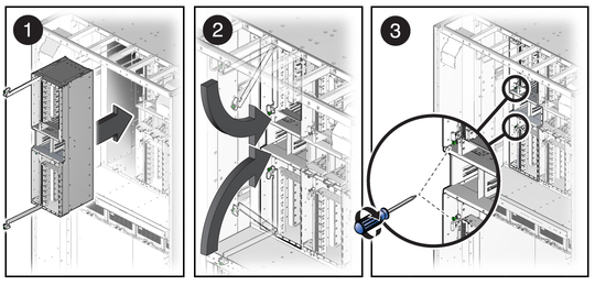
Squeeze the edges of a cover to release it from the connector.
 | Caution - The open extraction levers might slip down to eye level and pose a danger. Keep the levers closed and locked whenever possible. |

Keep the IOU as perfectly vertical as possible.
When the IOU is almost completely into the slot, stop when you feel some resistance.
 | Caution - There is a danger of bending pins in the connector at the back of the IOU. Do not hold the IOU at an angle when inserting it into the slot. |
Note - Because of the large number of connector pins at the rear of the IOU, it is normal to feel a larger than normal resistance as you seat the IOU. If you are not sure that you inserted the IOU at the proper angle (exactly 90° to the midplane), pull the IOU out and inspect the connector sockets and pins for damage. If there is no damage, try inserting the IOU again.
Tighten the screws to 15 in-lb. See Torque Reference.
Note - Install all components in their original locations.
For instructions, see Install a Hard Drive Cage.
For instructions, see Install an I/O Card in the Server .
For instructions, see Install an HDD.
For instructions, see Install an EMS
Leave some slack in the cables to allow the cables to be moved aside when necessary.
 | Caution - Tying I/O cables too tightly can damage them. |
See Return a Component to Oracle.
Include the plastic connector covers (Step 2) with the component.