Replacing a Disk Shelf SIM Board
 | Caution - Do not remove a component if you do not have an immediate replacement. The disk shelf must not be operated without all components in place, including filler panels. Refer to Disk Shelf Hardware Overview for component locations. |
The following disk shelves have SAS Interface Module (SIM) boards:
-
Sun Disk Shelf
The SIM boards, which are similar to I/O Modules, are hot-swappable so you can replace them without removing power to the system. The SIM boards are multi-pathed, so you can remove one of the SIM boards at any time, regardless of the state of the blue SIM OK indicator.
-
A faulted SIM board is indicated by an amber LED. Go to the Maintenance
> Hardware section of the BUI, click the right-arrow icon
 at the beginning of the appropriate disk shelf row, and
then click Slot to view details, or click the locator icon
  to turn on the locator LED.
- Locate the failed SIM at the back of the disk tray.
- Label and disconnect the tray interface cables.
- Use two hands to disconnect the SAS cable. Grasp the metal body of the connector with one hand and firmly grasp and pull the tab gently toward the connector body with the other, then pull the connector body outward to extract it from the bulkhead. Do not twist or pull the tab in any direction other than parallel with the connector body or it may break. If the tab breaks, use a small sharp object (such as a fine-tipped screwdriver) to lift the metal spring at the top of the connector shell to unlatch it.
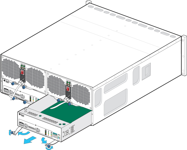
- Loosen the two extraction arm captive screws using your thumb and forefinger. If the captive screws are too tight to loosen by hand, use a No.2 Phillips screwdriver to loosen each screw.
-
Pull each ejector tab outward and push to the sides to release and
partially eject the SIM from the chassis.

- Grasp the middle of the SIM board and slide it out of the slot.
-
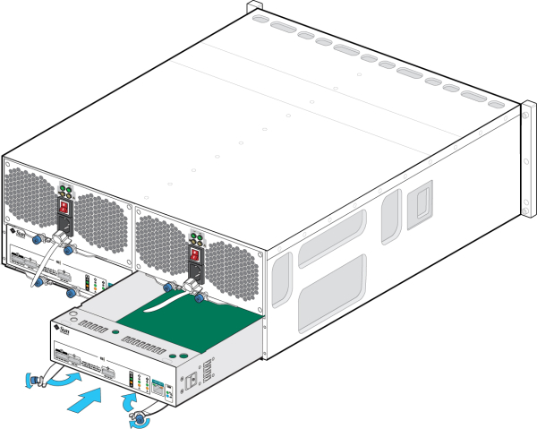
With the ejector arms in the full open position, align the new SIM board
with the open slot and slide it into the tray until the ejector arms contact
the tray connectors and begin to swing closed.

- Swing both ejector arms in until they are flush with the SIM board panel to seat the board.
- Tighten both captive screws to secure the board.
- Reconnect the SAS interface cables to their original locations.
- Wait approximately 60 seconds for the SIM board to complete its boot process, at which time the Power LED should be solid green and the SIM locate LED should be off.
-
Go to the Maintenance > Hardware section of the BUI, click the
right-arrow icon
 at the beginning of the appropriate disk shelf row, and
then click Slot to verify that the SIM board online icon
  is green for the newly installed SIM board.
- If a fault does not self-clear, see Repairing Active Problems.