Replacing a ZS5-2 Fan Module
Removing a fan module is a cold-service operation. You must power off the appliance before you remove the fan module. There will be a loss of access to the storage unless the system is in a clustered configuration. Use the following procedure to replace a ZS5-2 fan module.
-
Identify the faulted fan module.
-
If you are not physically at the system, go to the Maintenance > Hardware section of the BUI, click the right-arrow icon for the controller, click Fan, and note the ID of the faulted fan module, which has an amber icon. To highlight the location of the fan module in the controller picture, click on the fan module ID. To view details about the faulted fan module, click its information icon and then click Active Problems.
-
If you are physically at the system, note that each fan module has a fan fault LED that is located near the module on the motherboard. The amber LED is illuminated for failed fan modules.
-
- Power off the storage controller as described in Powering Off the Controller.
-
Disconnect the AC power cords from the rear panel of the storage
controller.

Caution - Because 3.3 VDC standby power is always present in the system, you must unplug the power cords before accessing any cold-serviceable components.
- Extend the controller from the rack as described in Extending the Storage Controller from the Rack.
- Remove the top cover as described in Removing the Top Cover.
-
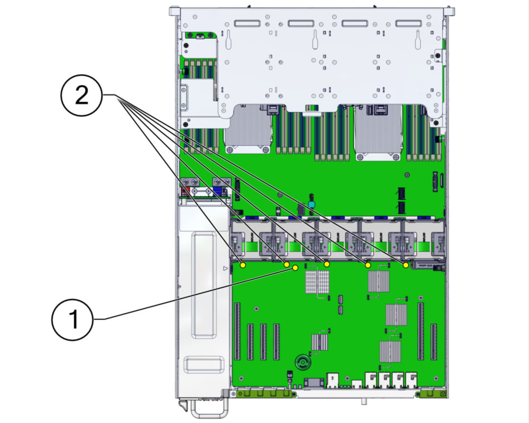
Press the Fault Remind button on the motherboard to illuminate the fan
module fault LED.
 No.Description1Fault Remind button2Fan Fault LEDs
 -
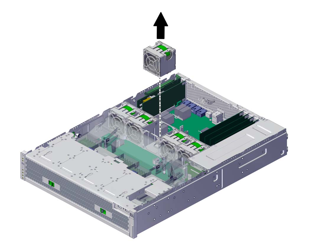
On the fan module to be replaced, pull the green band straight up to lift
the fan module out of the chassis, and set the module aside.

-
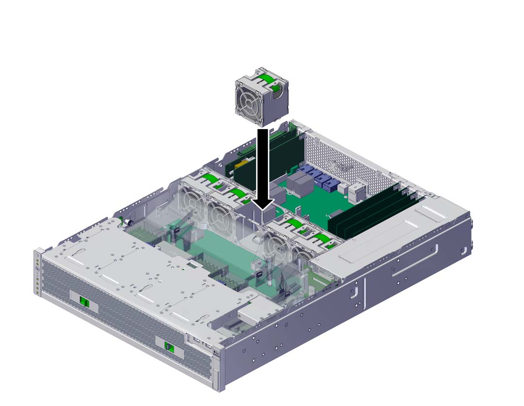
Align the replacement fan module with the fan tray slot.
The green band is on the top of the fan module and the arrow points to the rear of the chassis.
-
Lower the fan module into the fan tray.

-
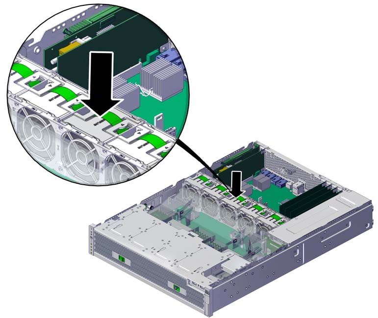
Press the fan module down until it clicks securely in the fan tray.

- Replace the top cover on the chassis, and tighten the two captive screws at the back of the top cover.
- Return the controller to the normal rack position by pushing the release tabs on the side of each rail while slowly pushing the storage controller into the rack.
- Connect the power cords to the power supplies. Verify that standby power is on, indicated by the Power/OK and SP status indicators flashing green on the front panel.
- Verify that the SP status and Power/OK indicators go solid green after the boot.
- Verify that the green OK indicator is lit on the fan module.
- Verify that the Fan indicator and the Service Action Required indicator on the front panel are not lit.
-
Go to the Maintenance > Hardware screen of the BUI. Click the
right-arrow icon for the controller, click Fan, and verify that the status
icon
 is green for the newly installed fan module. To view
details about the new fan module, click its information icon.
- If a fault does not self-clear, see Repairing Active Problems.