Go to main content

Oracle® SuperCluster M8 and SuperCluster M7 Installation Guide

Exit Print View

Updated: January 2019


IB Switch-to-Switch Cabling Reference

The IB switches are cabled together at the factory as shown in this figure and table.


Note - For information about IB switches, refer to the Sun Datacenter InfiniBand Switch 36 HTML Collection for Firmware Version 2.1 at http://docs.oracle.com/cd/E36265_01.

Note -  For information about interconnecting multiple racks, see Connecting Multiple SuperCluster M8 or SuperCluster M7 Systems and Connecting Expansion Racks.
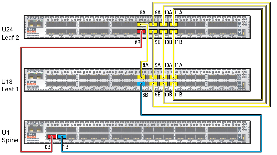
image:A figure showing the IB switch cable connections.
X = Factory Installed
From
Component
From
Location
From
Port
To
Component
To
Location
To
Port
X
Spine switch
U1
0B
Leaf switch 2
U24
8B
X
Spine switch
U1
1B
Leaf switch 1
U24
8B
X
Leaf switch 1
U18
8A
Leaf switch 2
U24
8A
X
Leaf switch 1
U18
9A
Leaf switch 2
U24
9B
X
Leaf switch 1
U18
9B
Leaf switch 2
U24
9A
X
Leaf switch 1
U18
10A
Leaf switch 2
U24
10B
X
Leaf switch 1
U18
10B
Leaf switch 2
U24
10A
X
Leaf switch 1
U18
11A
Leaf switch 2
U24
11B
X
Leaf switch 1
U18
11B
Leaf switch 2
U24
11A

Related Information