Compute
Server Cabled Components
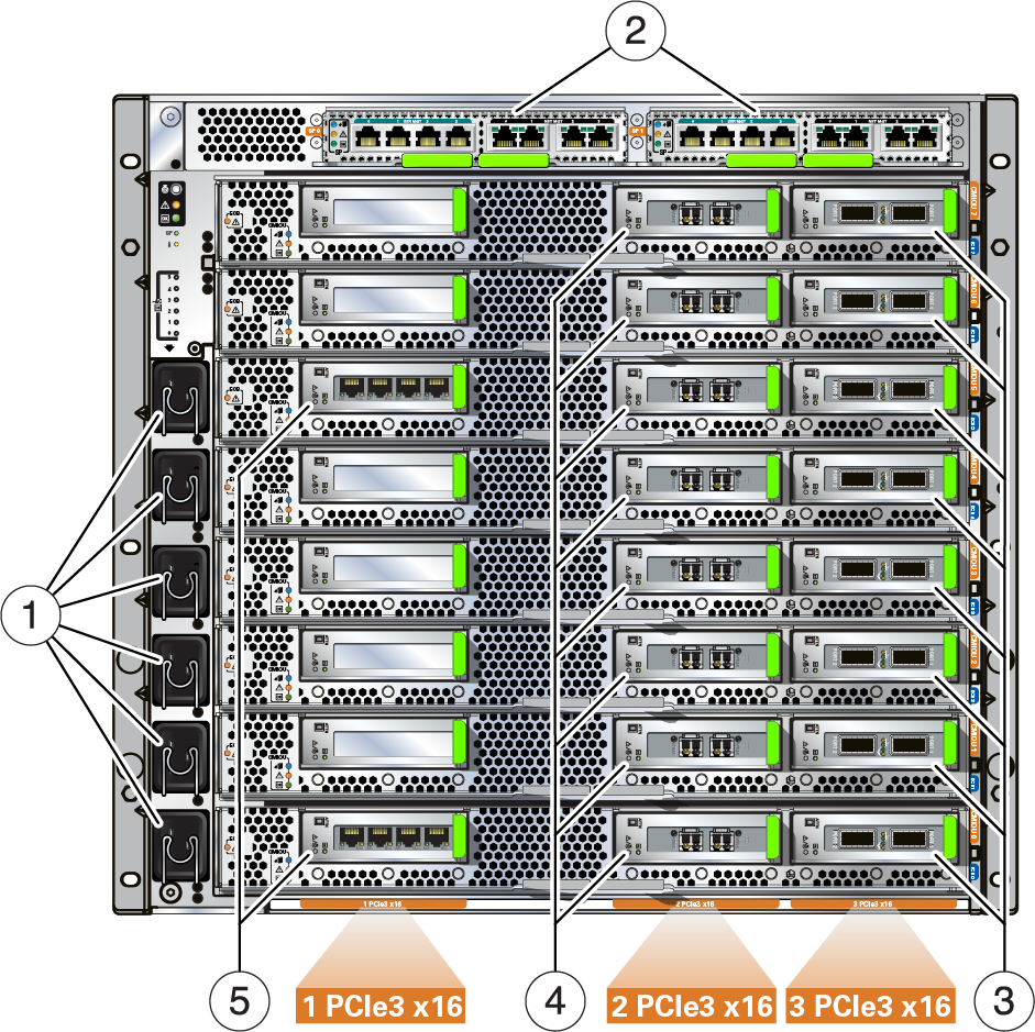
Use this illustration and table to identify the factory-cabled
compute server components.
The illustration shows network components for a compute server that is fully populated with
CMIOUs and PCIe cards. Other configurations have fewer components. For information on
all the types of configurations, refer to Oracle SuperCluster
M8 and SuperCluster M7 Overview Guide.
This figure shows the component locations for SuperCluster M7. SuperCluster M8 is similar with the differences are listed in the table.

|
|
|
|
|
1 |
6 power inlets per compute server |
U8 and optionally U27 |
Power cords. Receptacle varies based
on locale. |
|
2 |
2 SPs per compute server, each providing:
|
U17 and optionally U36 |
NET MGT – RJ-45, use Cat.5 or
better cables.
SER MGT – RJ-45, use serial cables. |
|
3 |
2, 4, or 8 IB HCA PCIe cards per compute
server, 2 ports per card |
Installed in the PCIe 3 carrier on each
CMIOU
|
Standard IB connectors supporting cables with QSFP+ connectors. |
|
4 |
SuperCluster M7: 1 10GbE dual-port PCIe card for each CMIOU
SuperCluster M8:
1 10GbE quad-port PCIe card for each CMIOU |
Installed in the PCIe 2 carrier on each
CMIOU |
SuperCluster M7: SFP+ optical splitter cable (10m, MPO to 4 LC)
SuperCluster M8:
QFSP+ optical Splitter Cable (10m, MPO/MTP to 2 LC) |
|
5 |
1 or 2 Sun Quad-Port GbE PCIe cards |
Installed in CMIOU 0, PCIe 1 carrier, and optionally in CMIOU 5, PCIe 1 carrier. |
RJ-45, use Cat.5 or better cables. |
|
|
