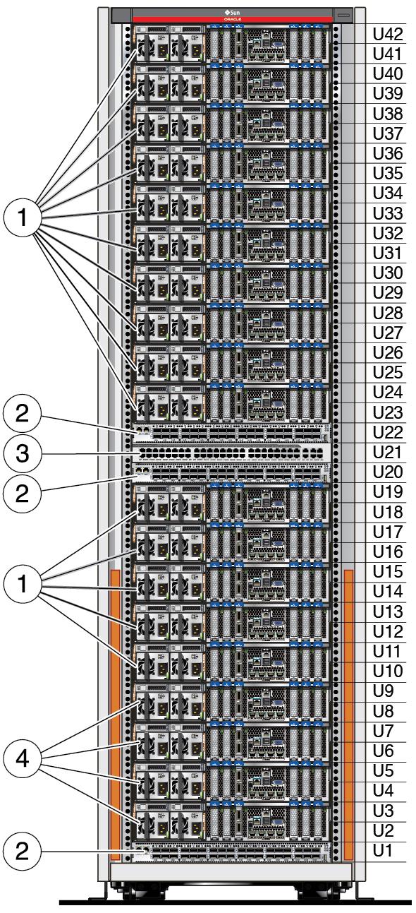
Expansion
Rack Components
Use this illustration and table to identify the locations
of the main components in the expansion rack.
This illustration shows a fully populated expansion rack.
Expansion racks might have fewer components.

|
|
|
|
|
1 |
(Optional) 1 to 15 additional storage servers
with these network components:
4 1GbE/10GbE ports
(NET 0, NET 1, NET 2, NET 3) 1 dual-port 4X QDR (40 Gb/s) IB HCA 1 SP Ethernet port for Oracle ILOM connectivity
|
U10 - U19
U23 - U42 |
10GbE uses CAT6A or better.
Other RJ-45 connections can use CAT5 or better cables.
IB ports use standard IB cables with QSFP connectors. |
|
2 |
3 IB switches |
U1 (spine)
U20 (leaf 1)
U22 (leaf 2) |
Standard IB cables with QSFP connectors. |
|
3 |
1 48-port 10/100/1000 Ethernet management
switch |
U21 |
RJ-45 uses CAT5 or better cables. |
|
4 |
4 storage servers, with these network components:
4 1GbE/10GbE ports
(NET 0, NET 1, NET 2, NET 3) 1 dual-port 4X QDR (40 Gb/s) IB HCA 1 SP Ethernet port for Oracle ILOM connectivity
|
U2 - U9 |
10GbE uses CAT6A or better.
Other RJ-45 connections can use CAT5 or better cables.
IB ports use standard IB cables with QSFP connectors. |
|
|

