Go to main content
Oracle® ZFS Storage ZS5-ES Service Manual, Release OS8.6.x

Exit Print View

Updated: March 2017


Illustrated Parts Breakdown

The following figure identifies the major components of the controller.

Figure 3  Controller Illustrated Parts Breakdown
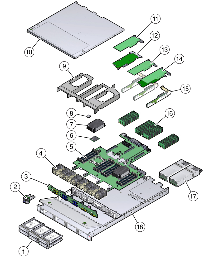
image:Figure showing exploded view of the system components.

Callout
Description
Callout
Description
1
Two system drives and two optional read cache SSDs
10
Top cover
2
Front indicator module (FIM)
11
Cluster interface card Version 3 (PCIe slot 3)
3
Disk backplane
12
Internal SAS-3 HBA card (PCIe slot 4)
4
Fan modules
13
External SAS-3 4-port (4x4) HBA (PCIe slot 2)
5
Motherboard
14
InfiniBand HCA (PCIe slot 1)
6
Processors
15
PCIe risers (3)
7
Heatsinks
16
DIMMs
8
Battery
17
Power supplies
9
Air baffle
18
Controller chassis