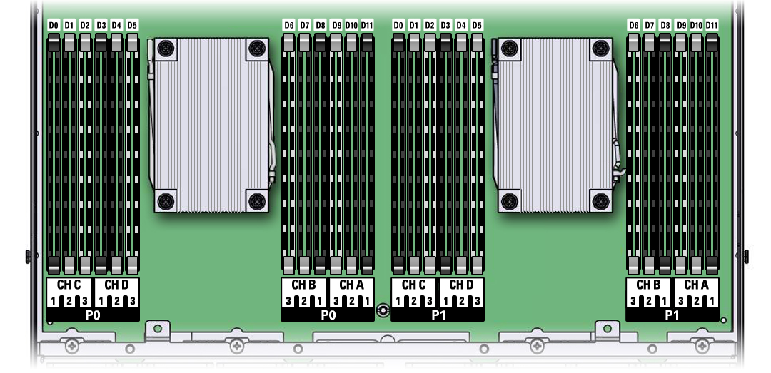
DIMM and Processor Physical Layout
The physical layout of the DIMMs and processors is shown in the following figure. When viewing the controller from the front, processor 0 (P0) is on the left. Notice that each processor, P0 and P1, has four memory channels that are labeled, from left to right, Ch C, Ch D, Ch B, and Ch A.
Figure 7 DIMM and Processor Physical Layout
