Install the Motherboard
 | Caution - The motherboard should be installed only by authorized Oracle Services personnel. |
- Attach an antistatic wrist strap to your wrist, and then to a metal area on the chassis.
-
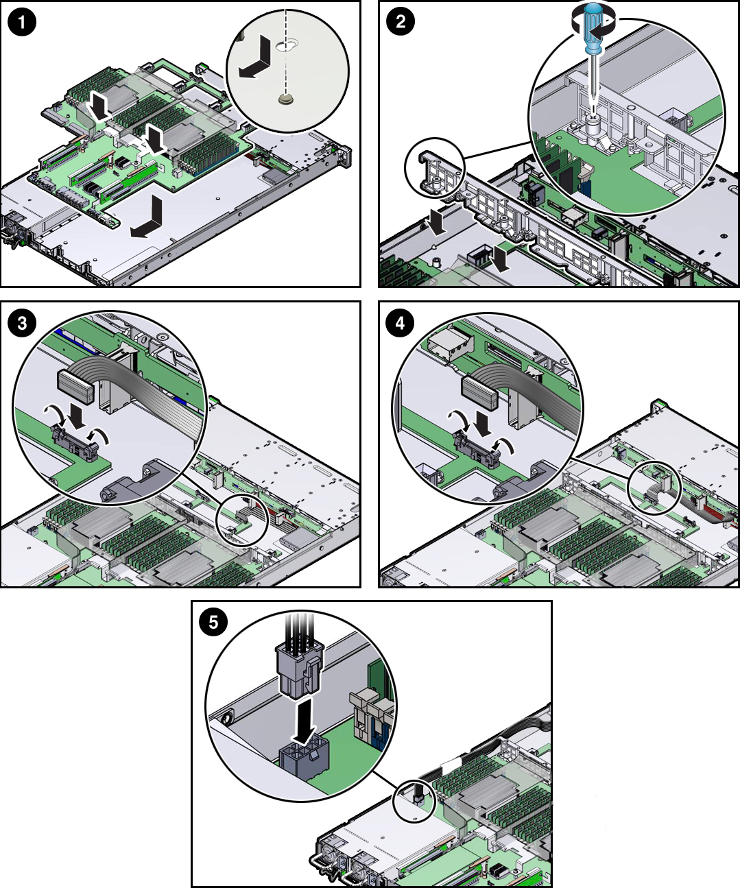
Insert the motherboard into the controller chassis [1].
- Grasp the metal bracket located to the rear of the DIMMs and slightly tilt up the front of the motherboard. Push the motherboard into the opening in the rear of the controller chassis.
- Lower the motherboard into the controller chassis and slide it to the rear until it engages the seven mushroom-shaped standoffs located on the controller chassis under the motherboard.
-
Ensure that the indicators, controls, and connectors on the rear
of the motherboard will fit correctly into the rear of the
controller chassis [1]. Lower the motherboard onto the bottom
alignment pins.

-
Install the controller mid-wall [2].
-
Lay the SAS cables along the left chassis sidewall (viewing the
controller form the front).
You will connect these cables to the internal HBA card later.
- Position the mid-wall over the front of the motherboard so that it engages the mushroom-shaped standoffs that are located on the controller chassis sidewall (one for each end of the mid-wall).
- Ensure that SAS cables are not pinched by the mid-wall and that they run beside the mid-wall and not under it; otherwise, the cables might be damaged.
- To secure the mid-wall to the controller chassis, use a screwdriver (No. 2 Phillips or flathead) to tighten the four captive screws.
-
Lay the SAS cables along the left chassis sidewall (viewing the
controller form the front).
-
To install the front indicator module (FIM) cable, push the side latches
on the motherboard connector to the open position and push the FIM cable
connector in [3].
The side latches close, locking the connector in place.
- Reconnect the disk backplane auxiliary power and signal cable to the motherboard [4].
- Reconnect the disk backplane power cable to the motherboard [5].
-
Reinstall the following components:
- PCIe risers and attached PCIe cards
-
Fan modules
See Install a Fan Module.
- Return the controller to operation.