Populating DIMMs in Single-Processor Systems for Optimal System Performance
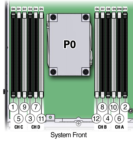
In single-processor systems, install DIMMs only into DIMM sockets associated with processor 0 (P0). Starting with socket P0 D0, first filling the black sockets, then the black sockets with white tabs, and then the white sockets, as shown in the following figure. Notice that the order of populating the black sockets is Ch C first, Ch A second, Ch D third, and Ch B last. Repeat the same population sequence for the black sockets with white tabs, and finally for the white sockets.
Figure 4 DIMM Population Order for Single-Processor Systems

The following table describes the proper order in which to populate DIMMs in a single-processor system using the numbered callouts in the above figure, the memory channel labels (Ch A through Ch D), and the DIMM socket labels (D0 through D11).
| ||||||||||||||||||||||||||||||||||||||||||||||||