Inspect the Server and Install Optional Components
This procedure provides instructions for inspecting the server and installing optional components before you install the server in the rack.
 | Caution - Electrical hazard. Ensure that the server is disconnected from the power source. |
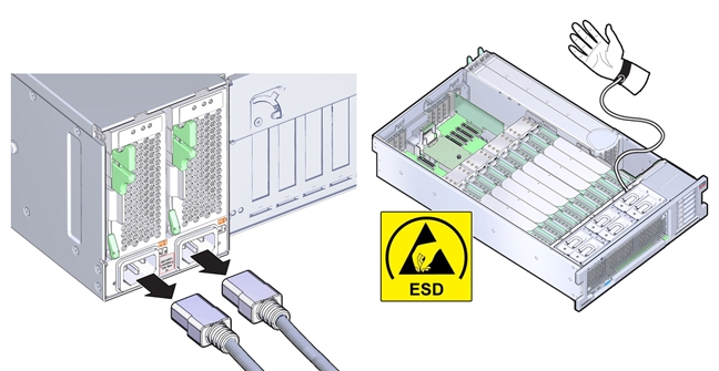
 | Caution - Component damage. The server contains components that are sensitive to electrostatic discharge. When working inside the server, wear an antistatic wrist strap and use an antistatic mat. |
Before You Begin
- Ensure that the server is disconnected from the power source.
- Use an antistatic wrist strap that it is secured to a grounded surface.
-
Remove the server top cover.
-
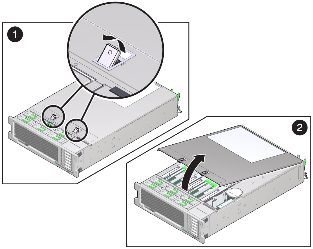
Lift the two spring-loaded latches on top of the cover to their fully open position and pull
the front edge of the cover upward.
In the following illustration, frame 1 shows the two spring-loaded latches lifted to their fully open position, and frame 2 shows the cover pulled up and away from the server.
-
Remove the cover from the server and set it aside.

Caution - Component damage. An interlock switch component is attached to the underside of the server cover. Take care not to damge the component.
-
Lift the two spring-loaded latches on top of the cover to their fully open position and pull
the front edge of the cover upward.
-
Ensure that all replaceable components and cable connectors are seated and locked in place. If
necessary, reseat (remove and install) components.
For component removal and installation procedures, refer to the service label on the top cover of the server or the component removal and replacement procedures in the Oracle Server X5-4 Service Manual
The following illustration shows the location of replaceable components.
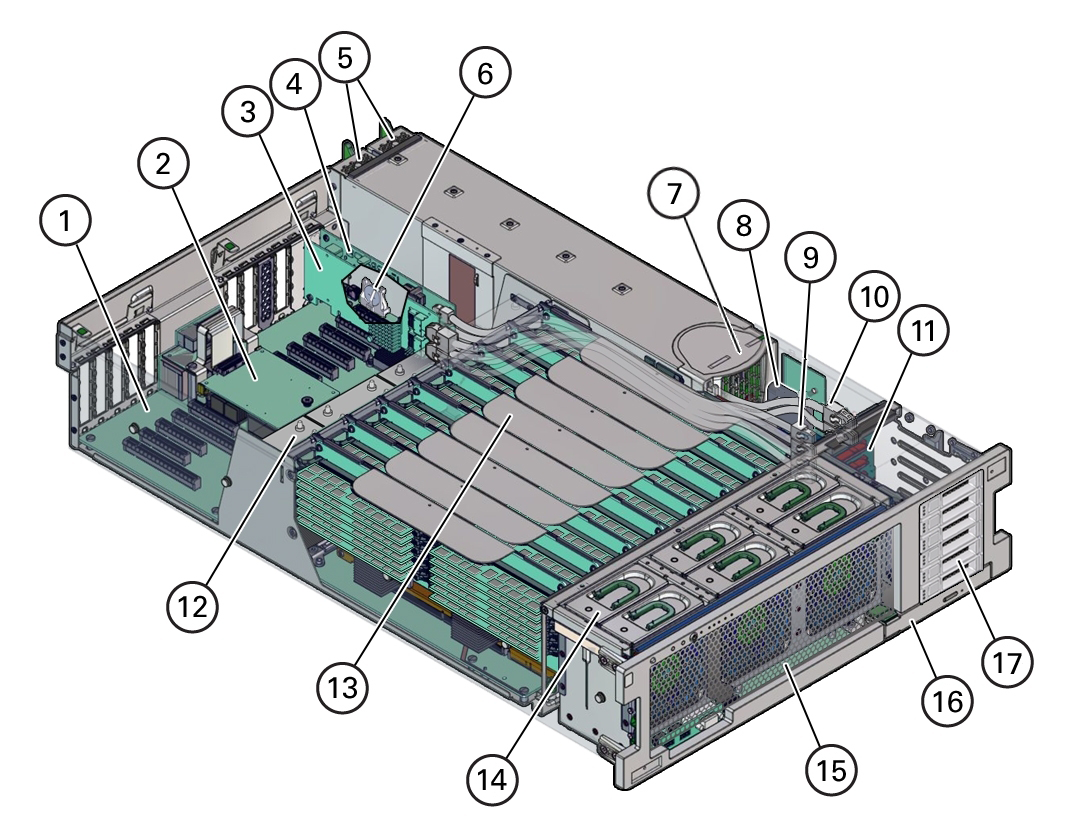 Call OutDescriptionCall OutDescription1Motherboard10HBA SAS cables (2)2SP card11Storage drive backplane board3HBA card12Heatsinks and CPUs (2 or 4)4PCIe NVMe Switch card13Memory riser cards (4 or 8)5Power supplies (2)14Fan modules (6)6System battery15Fan board7Power supply backplane16DVD Drive8ESM17Storage drive slots (6)9NVMe cables (4)
 -
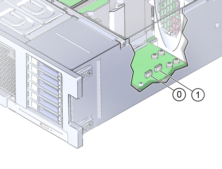
Check that the Oracle System Assistant USB flash drive is installed.
If you ordered Oracle System Assistant, check that the dedicated USB flash drive is installed in the internal USB port, P0. The following illustration, shows the two internal USB ports, which are located behind the storage drives. USB port P0 is located next to USB port P1 but closer to the front of the server
-
Install optional components.
Install any optional components that might have been shipped separately. Optional components include:
-
PCIe cards
-
DDR3 DIMM memory kits
-
Storage drives
To install optional components, refer to the service label on the top cover of the server or the component removal and replacement procedures in the Oracle Server X5-4 Service Manual
-
-
Install the server cover.
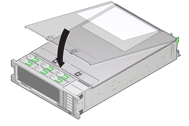
- Align the cover on top of the server, ensuring that the back end of the cover is secured under the lip on the rear edge of the server.
- Lower the front edge of the cover until it is flat on the server.
- Push down on the front edge until the latches lock into place with an audible click.
- Verify that the cover is locked.