Supported DIMMs and DIMM Population Rules
This section describes the supported DIMM configuration and population rules for memory risers in the system. Use only Oracle supported DIMMs in the system.
Supported configurations:
-
Minimum supported configuration:
-
Two or Four-CPU system:
Two DDR3 (Double Data Rate 3) 16 GB low voltage RDIMMs (Registered Dual In-Line Memory Modules) installed in each memory riser (slots D0 and D3).
-
-
Maximum supported configuration:
-
Two-CPU system:
Up to 48 DDR3 low voltage RDIMMs or LRDIMMs (Load Reduced Dual In-Line Memory Modules) are supported.
-
Four-CPU system:
Up to 96 DDR3 low voltage RDIMMs or LRDIMMs are supported.
-
Supported DIMM types and sizes available from Oracle:
Note - DIMM system performance speed maximum is 1333 MHz (even if the DIMM is rated higher).
|
Population rules:
-
Only one type and size DIMM is supported in the system at any time. Mixing DIMMs of different size or technology (such as RDIMMs and LRDIMMs) is not supported.
-
When upgrading to a different size DIMM, replace all DIMMs in the system to match the new capacity.
-
All memory riser cards must be populated identically.
-
Install DIMMs in the following sequence for each memory riser card (refer to the illustrations that follow for additional details):
-
For a system with the minimum configuration (two DIMMs per riser), add two more DIMMs to memory riser slots D6 and D9 for each memory riser in the system. The end result being that DIMM slots D0, D3, D6 and D9 (black/black slots) are all populated. This provides a one DIMM per channel configuration across both memory buffers.
Additional memory upgrades are done in increments of four DIMMs per riser, as follows:
-
Next, populate riser slots D1, D4, D7 and D10 (black/white slots). This provides a two DIMM per channel configuration.
-
And finally, populate riser slots D2, D5, D8 and D11 (white/white slots). This provides a three DIMM per channel configuration.
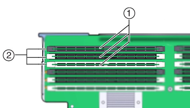
The memory slots and ejector levers are color coded using a black and white color scheme to aid in installation. Slots can have a black slot with black levers (black/black slots), black slot with white levers (black/white slots), or white slot with white levers (white/white slots) as shown in the following illustration:
 Call OutDescription1Slots2Levers
 -
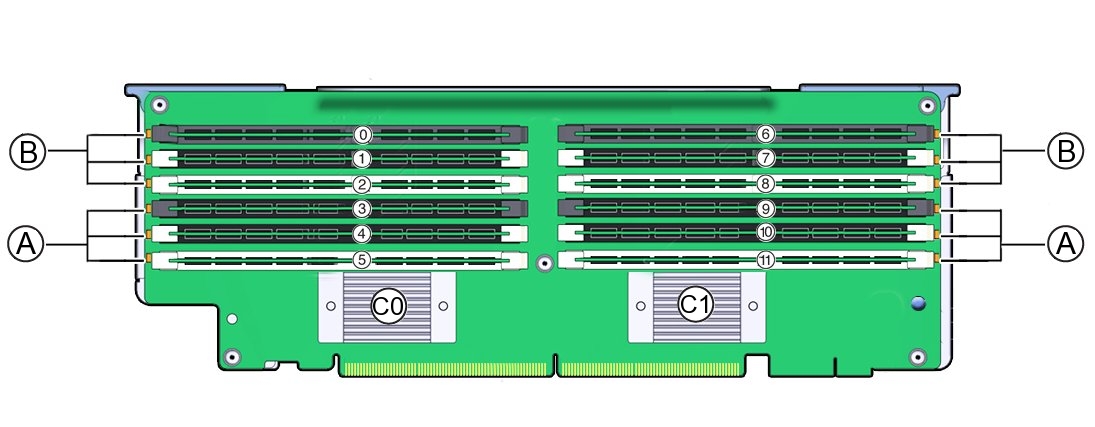
Memory Riser layout:
The following illustration shows the DIMM slot and channel designations on the memory riser card:

|