Replace the Power Supply Backplane Board (FRU)
When servicing the components in this section, unplug the AC power cords and use ESD protection.
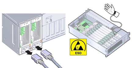
 | Caution - Hazardous voltage. The system supplies power to the power board even when the server is in standby power mode. Disconnect power cords before servicing the power supply backplane board. |
Before You Begin
-
For serviceability considerations, see Component Serviceability.
- Prepare the server for service. See Prepare the Server for Cold Service.
- Disconnect the SAS/SATA cables from the disk drive backplane and the HBA.
-
Remove all PCIe cards from the server taking care to note their slot assignments. See Remove a PCIe Card.
Make a note of where each PCIe card installed so they can be put back in the same slots. The internal SAS/SATA cables do not need to be removed, but must be out of the way as the motherboard needs to be removed.
-
If the server has two CPUs, carefully remove the air baffle, taking care not to damage the fan
board ribbon cable.
Lift the baffle slowly and maneuver its front edge away from the ribbon cable while removing.

Caution - Component damage. Lifting the baffle straight up from the server can damage the fan board ribbon cable. The front support foot for the air baffle is located under the cable.
- Remove all memory riser cards. See Remove a Memory Riser Card.
- Disconnect the fan board data and power cables from the motherboard.
- Disconnect the power supplies from the power supply backplane connectors by removing both power supplies at least part way out of the chassis. See Remove a Power Supply.
-
Move the air divider.
The air divider that separates the disk drive backplane area from the rest of the chassis (and includes the system Fault Remind button mechanism) must be moved to allow access to the power supply backplane board and allow removal of the motherboard. The air divider is mounted to the power supply side wall using two tabs which are inserted into slots in the side wall. For this procedure, you can leave the cables attached to the air divider.

Caution - Hardware damage. Try not to allow the SAS cables to rub against the CPU0 heatsink radiator fins. They are sharp and can damage the cable insulation.
- Lift the air divider so the tabs clear the slots in the power supply side wall.
- Move the air divider away from the side wall and gently rotate the divider and the cables attached to it away from the backplane area and set it in the empty memory riser area.
- Disconnect the disk drive backplane power and data cables from the disk drive backplane.
- Remove the ribbon cable connecting the power supply backplane to the motherboard.
-
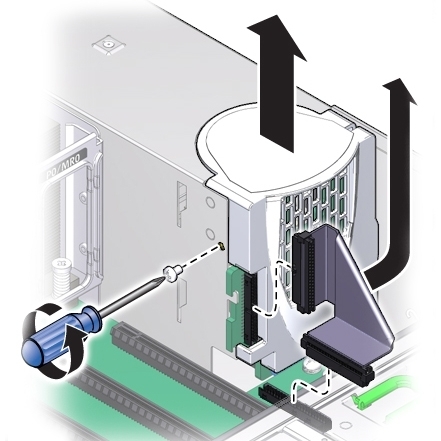
Remove the screw holding the power supply cover in place and remove the power supply
cover.
-
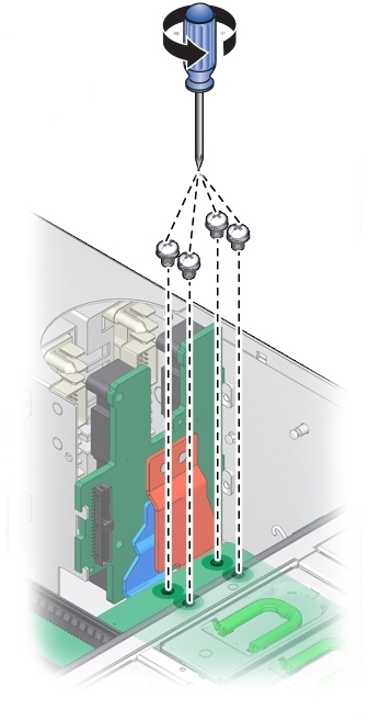
Remove the four screws securing the power supply backplane bus bar to the motherboard.
The backplane board rests on the two support flanges. The bus bars are attached at contact pads underneath the motherboard.
-
Loosen the green captive screw that secures the motherboard to the chassis.
The screw is located at the left front corner of the motherboard behind FM3.

-
To unlock the motherboard, use the memory riser card guide by the processors and the handle
above the SP card slot to slide the motherboard toward the front of the server.
This action unlocks the motherboard and plate assembly.
Note - As you slide the motherboard forward, check that the Locator indicator light pipe extension piece slides out of its hole in the chassis back wall. -
While gently sliding it away from the back of the server, carefully lift the front end of the
motherboard several inches.
Note - If Locator indicator light pipe extension detaches during removal, ensure that you retrieve it from the server. The extension is a clear plastic piece that transmits light and allows you to activate the Locator indicator switch from the back of the server.
-
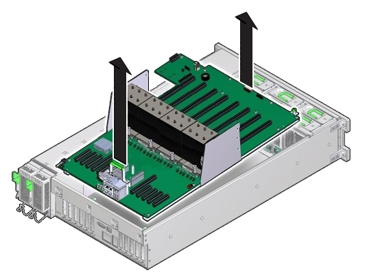
To remove the motherboard, slowly guide it up and out of the server.
-
Lift out the power supply backplane board from its support flanges and out of the
chassis.

-
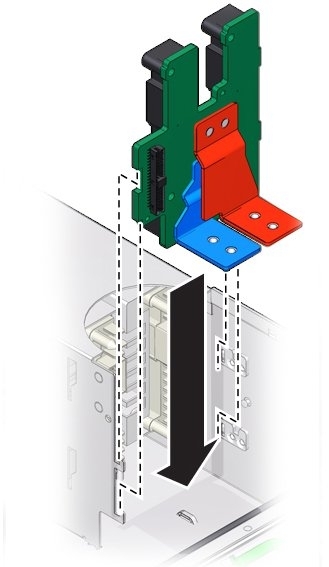
Insert the replacement power supply backplane board into the server. The tabs on the power
board must slide onto the flanges on the power supply cage.
-
Lower the motherboard into the server and guide the light pipe extension piece for the Locator
indicator at the back of the motherboard into its hole on the server back wall.
This should also align the bus bar holes on the motherboard to the power supply backplane bus bar connector holes.
Note - Ensure that the red and blue bus bar connectors are under the motherboard bus bar connection pads.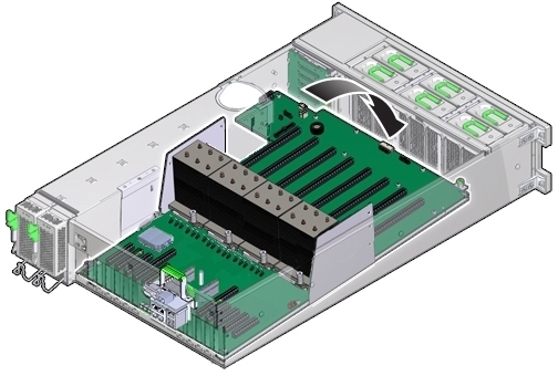
- Ensure that the Locator indicator switch at the back of the server operates easily and is not stuck in the depressed position.
-
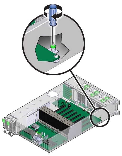
To secure the motherboard to the chassis, tighten the captive screw.
-
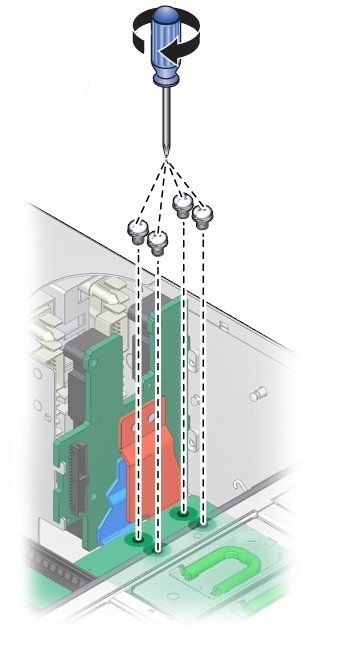
Use the four screws to secure the bus bar to the motherboard.
-
Connect the ribbon cable from the motherboard to the power supply backplane.
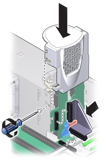
- Replace the power supply cover and fasten it in place with the screw.
- Connect the data and power cables from the fan board to the motherboard.
- Connect the disk drive backplane power cable and ribbon data cable.
-
To install the air divider:
Note - The air divider contains the Fault Remind button mechanism. To ensure that the mechanism can engage the motherboard-mounted switch, the divider must be installed correctly.- Align the two tabs on the divider with the two slots in the power supply side wall.
-
Push the tabs into the slots and push the air divider downward to secure it against the
wall.
To ensure proper alignment of the Fault Remind switch, both tabs must be engaged with their slots.
-
Ensure the SAS/SATA cables are routed through the slot in the air divider.
The back side of the divider has enough room to house the cables if they are flat and side-by-side. Do not allow the cables to interfere with the Fault Remind button mechanism.
-
Connect the SAS/SATA cables to the disk drive backplane.
The mini-SAS plug that terminates the short SAS/SATA cable must be inserted into the upper mini-SAS connector on the disk backplane. This short cable connects the SATA DVD to its USB-SATA bridge on the motherboard. The longer SAS/SATA cable connects drive bays 4 and 5 to a storage device in the back of the system. The lower mini-SAS connector on the disk backplane requires the standard, four-channel mini-SAS cable for drive bays 0 to 3.
- Install all memory risers.
- For a two-CPU system, install the air baffle, ensuring that the foot on the front of the baffle is under the fan board ribbon cable.
-
Install all PCIe cards.
See Install a PCIe Card.
Note - During the process of reinstallation of the HBA card, it might be easier to reconnect the SAS/SATA cables before installing the card in its PCIe slot. - Install the power supplies. See Install a Power Supply.
- Prepare the server for operation. See Prepare the Server for Operation.