Replace the Fan Board (FRU)
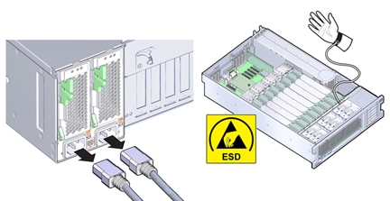
When servicing the components in this section, unplug the AC power cords and use ESD protection.
Before You Begin
-
For serviceability considerations, see Component Serviceability.
- Prepare the server for service. See Prepare the Server for Cold Service.
-
Remove all fan modules.
See Remove a Fan Module.
- Remove all memory risers.
- Disconnect any cables plugged into the USB or video connectors on the front of the server.
-
Remove the fan board:
-
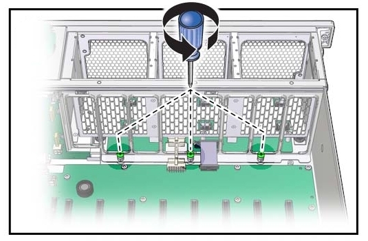
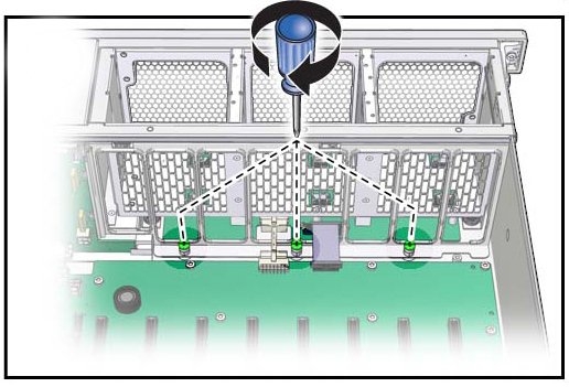
Loosen the three captive screws connecting the front-side memory riser guide to the
motherboard.
-
Remove the two screws on each side of the outside of the chassis that hold the fan board unit
in place.
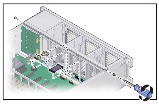
- Unplug the fan board cable and power cables from motherboard.
-
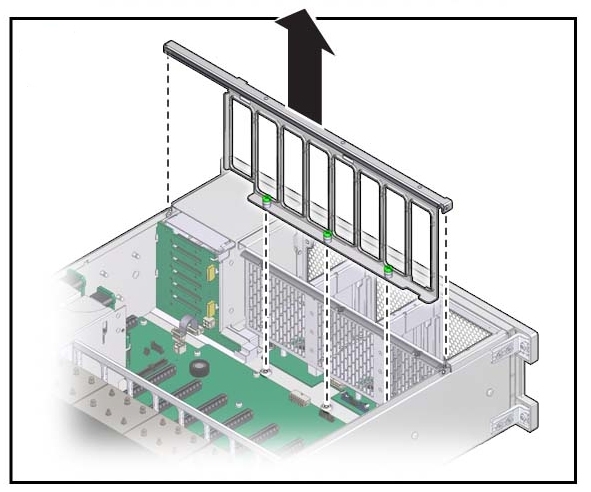
Remove the front memory riser guide by pulling it up and out of the chassis.
-
To remove, slide the fan board cage away from the front of the server (to clear the lip at the
front of the chassis) and lift it out of the server.
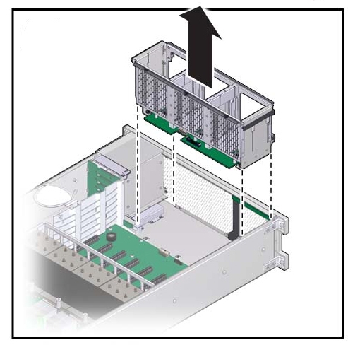
-
Loosen the three captive screws connecting the front-side memory riser guide to the
motherboard.
- Remove the fan board cable and power cables from the faulty fan board unit and plug them into the fan board on the replacement fan board unit.
-
To install the fan board unit:
-
Insert the fan board unit into the chassis, moving it down and toward the front.
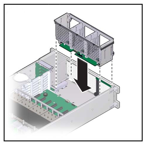
-
Reposition the front memory riser guide, routing the fan board and power cable through the
riser guide.
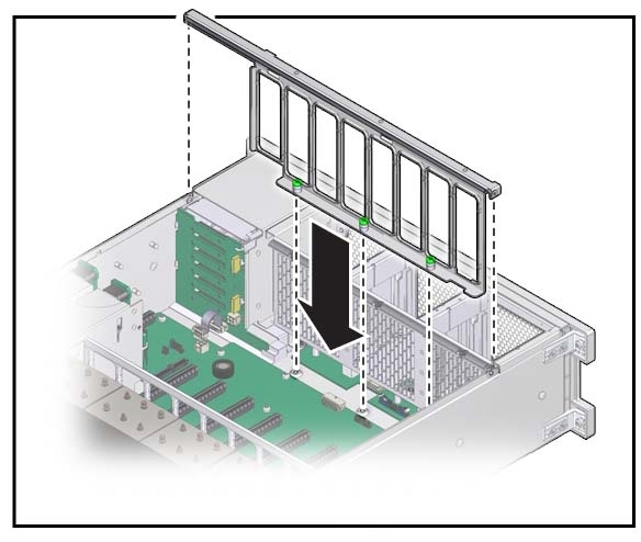
-
Connect the fan board cable and power cable into the connectors on the motherboard and
partially tighten the two screws that secure the riser guide to the chassis.
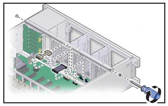
-
Tighten the three captive screws to hold the front memory riser guide in place.
- To secure the fan board unit in place, fully tighten the two screws that secure the riser guide to the chassis.
-
Insert the fan board unit into the chassis, moving it down and toward the front.
-
Install the fan modules.
See Install a Fan Module.
- Install the memory risers.
-
Prepare the server for operation. See Prepare the Server for
Operation.
Note - The product serial number used for service entitlement and warranty coverage might need to be reprogrammed by authorized service personnel with the correct product serial number.