Go to main content

Oracle® ZFS Storage Appliance Customer Service Manual

Exit Print View

Updated: November 2018


7420 Front and Back Panel Components

7420 Front Panel Components - The 7420 controller drive slots and front panel components are shown in the following figure.

Figure 50  7420 Controller Front Panel
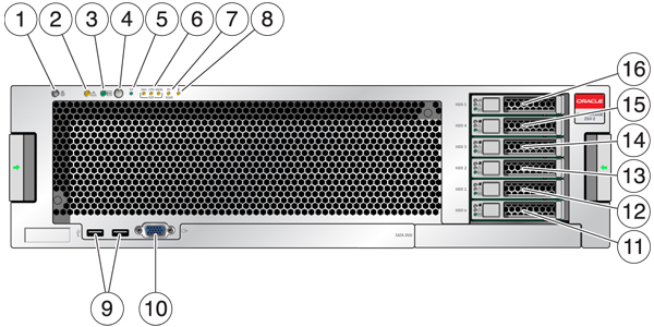
image:graphic showing 7420 controller front                                                 panel

Figure Legend
Figure Legend
Figure Legend
1 Locator LED and button (white)
7 Power Supply (PS) Service Required LED
13 SSD 2 (optional)
2 Service Required LED (amber)
8 Over Temperature Warning LED
14 SSD 3 (optional)
3 Power/OK LED (green)
9 USB 2.0 Connectors
15 SSD 4 (optional)
4 Power button
10 DB-15 video connector
16 SSD 5 (optional)
5 Service Processor (SP) OK LED (green)
11 Boot drive 0 (mirrored)
6 Fan/CPU/Memory Service Required LED
12 Boot drive 1 (mirrored)

7420 Back Panel Components - The following graphic shows the rear panel of the controller. Base configuration HBAs are not depicted in this illustration.

Figure 51  7420 Controller Rear Panel
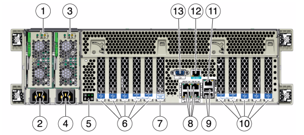
image:graphic showing 7420 controller rear                                                 panel

Figure Legend
Figure Legend
1 Power supply unit 0 status LEDs OK: green Power Supply Fail: amber AC OK: green
8 Network (NET) 10/100/1000 ports: NET0-NET3
2 Power supply unit 0 AC inlet
9 USB 2.0 ports
3 Power supply unit 1 status LEDs OK: green Power Supply Fail: amber AC OK: green
10 PCIe slots 5-9
4 Power supply unit 1 AC inlet
11 Network management (NET MGT) 10/100 BASE-T Ethernet port
5 System status LEDs Power: green Attention: amber Locate: white
12 Serial management (SER MGT) port
6 PCIe slots 0-4
13 DB-15 video connector
7 Cluster card slot

Cluster Interface Card Compatibility - The 7420 controller contains a Version 2 cluster interface card. This card cannot be replaced with a Version 3 cluster interface card.

For information about how to connect cables to form a cluster, see Connecting Cluster Cables in Oracle ZFS Storage Appliance Cabling Guide.

Ethernet Ports

There are four RJ-45 Gigabit Ethernet connectors (NET0, NET1, NET2, NET3) located on the motherboard that operate at 10/100/1000 Mbit/sec. These network interfaces must be configured before use.

Network Management Port

The network management connector (NET MGT) is an RJ-45 10/100 BASE-T Ethernet port and provides a LAN interface to the SP console.

Figure 52  7420 Controller Network Management Port

image:graphic showing 7420 controller network management port

Serial Management Port

The serial management connector (SER MGT) is an RJ-45 connector and provides a terminal connection to the SP console.

Figure 53  7420 Controller Serial Management Port

image:graphic showing 7420 controller serial management port