Replacing a ZS3-2 Power Supply
Storage controllers are equipped with redundant hot-swappable power supplies. If a power supply fails and you do not have a replacement, leave the failed power supply installed to ensure proper air flow. A faulted power supply is indicated by an amber colored status LED. Use the following procedure to replace a ZS3-2 power supply.
- Gain access to the rear of the storage controller where the faulted power supply is located.
-
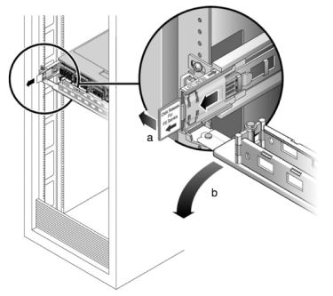
If a cable management arm (CMA) is installed, press and hold the CMA
release tab and rotate the arm out of the way.

- Disconnect the power cord from the faulted power supply.
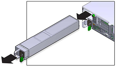
- Press the release tab to the left and pull on the handle.
-
Continue to pull on the handle to slide the power supply out of the
chassis.

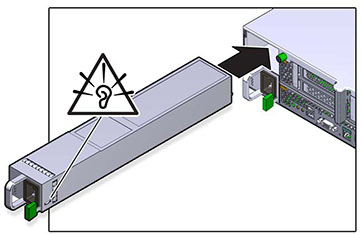
- Align the replacement power supply with the empty power supply chassis bay.
-
Slide the power supply into the bay until the power supply seats and the
release tab clicks.

- Push the release tabs on the side of each rail and slowly push the storage controller into the rack, making sure no cables obstruct the path of the controller.
- Reconnect all cables to their original ports, referring to the labels previously added as a guide. For cabling details, see the Oracle ZFS Storage Appliance Cabling Guide .
- Connect the power cords to the power supplies. Verify that standby power is on, indicated by the Power/OK and SP status indicators flashing green on the front panel.
- After the SP indicator is solid, use a pen or other pointed object to press and release the recessed Power button on the front panel. The Power/OK status indicator next to the Power button lights and remains lit.
- Close the CMA, inserting the CMA into the rear left rail bracket.
-
Go to the Maintenance > Hardware screen of the BUI. Click the
right-arrow icon
 for the controller and then click PSU to verify that
the online icon
  is green for the newly installed power supply.
- If a fault does not self-clear, see Repairing Active Problems.