Replacing or Adding a ZS7-2 PCIe Card
 | Caution - This procedure requires that you handle components that are sensitive to static discharge, which can cause the component to fail. To avoid damage, wear an antistatic wrist strap and use an antistatic mat when handling components. |
Replacing or adding a PCIe card is a cold-swap procedure, and you must remove power from the controller. If you are installing a newly released adapter, upgrade your system software before installing the adapter as described in Upgrading the Software. Use the following procedure to replace or add a ZS7-2 PCle card.
-
Identify the PCIe card slot location.
-
If replacing a faulted PCIe card, identify the PCIe card to be replaced.
Go to the Maintenance > Hardware section of the BUI, click the right-arrow icon for the controller, click Slot, and note the ID of the faulted PCIe card, which has an amber icon. If replacing a non-faulted PCle card, note its location. To highlight the location of the card in the controller picture, click on the card ID. To view details about the card, click its information icon and then click Active Problems.
-
If adding a new PCIe card, identify the correct slot location as described in ZS7-2 PCIe Card Configuration.
-
- Shut down the controller using one of the power-off methods described in Powering Off the Controller.
-
Disconnect the AC power cords from the rear panel of the controller.

Caution - Because 3.3 VDC standby power is always present in the system, you must unplug the power cords before accessing any cold-serviceable components.
- Extend the controller from the rack as described in Extending the Controller from the Rack.
- Remove the top cover as described in Removing the Controller Top Cover.
-
Locate the PCIe card position in the controller.
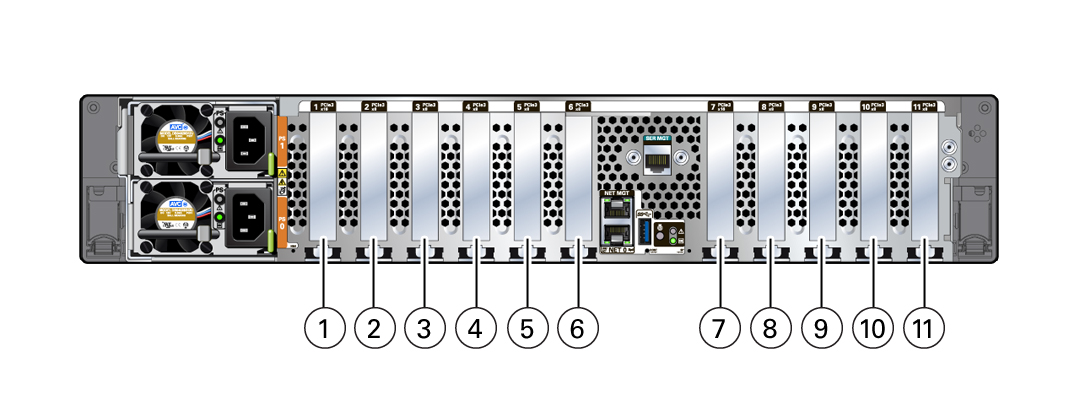
There are 11 PCIe slots available for PCIe cards. The following figure shows the PCIe slot numbering.
 CalloutDescription1PCIe slot 1: Fifth PCIe option2PCIe slot 2: External SAS-3 HBA3PCIe slot 3: High-end model: External SAS-3 HBA; Mid-range model: Filler panel4PCIe slot 4: First PCIe option5PCIe slot 5: Third PCIe option6PCIe slot 6: Cluster interface card7PCIe slot 7: Fourth PCIe option8PCIe slot 8: Second PCIe option9PCIe slot 9: High-end model: External SAS-3 HBA; Mid-range model: Filler panel10PCIe slot 10: External SAS-3 HBA11PCIe slot 11: Internal SAS-3 HBA
Note - All of the PCIe slots comply with the PCI Express 3.0 specification and can accommodate 25 Watt PCIe3 cards. -
Unplug all data cables from the PCIe card.
Note the cable connections in order to ease proper reconnection of the cables. If the PCIe card has transceivers, remove them before removing the PCIe card from the controller.
-
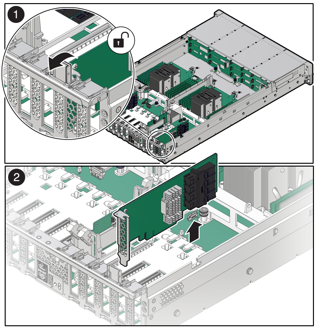
Rotate the PCIe card locking mechanism into an upright position [1], and then
lift up on the PCIe card to disengage it from the motherboard connectors
[2].

-
Place the PCIe card on an antistatic mat.

Caution - If you are not immediately inserting a replacement PCIe card into the empty slot, insert a PCIe filler panel in the slot to reduce the possibility of radiated electromagnetic interference (EMI), or the overheating of the controller due to improper airflow.
-
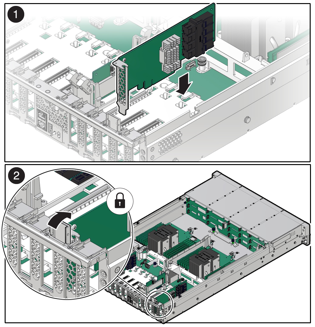
Insert the PCIe card into the correct slot [1], and rotate the PCIe locking
mechanism downward to secure the PCIe card in place [2].
You will hear or feel a click when the PCIe card is secured into the slot.

- Replace the top cover on the chassis.
-
Return the controller to the normal rack position by
pulling
the
green
release tabs on the side of each rail while slowly pushing the controller into the
rack.
If the installed PCIe card requires transceivers, install them now.
-
Reconnect all cables to their original ports, referring to the labels
previously added as a guide. For cabling details, see the
Oracle ZFS Storage Appliance Cabling
Guide
.
If you replaced an HBA, connect the disk shelves to its ports as described in Oracle ZFS Storage Appliance Cabling Guide .
- Reconnect the power cords to the power supplies.
- Verify that standby power is on. Approximately two minutes after plugging in the power cords, the Power/OK status indicator on the front panel starts flashing.
-
After the
Power/OK status indicator is flashing, press and release the
recessed Power button on the controller front panel.
The Power/OK status indicator continues flashing during the startup sequence, which takes several minutes. When the system is operational, the indicator remains lit.
-
After the
Power/OK status indicator is lit steadily, log in and go to the
Maintenance > Hardware screen of the BUI. Click the right-arrow icon for the
controller, click Slot, and verify that the status icon
 is green for the newly installed card. To view details about
the new card, click its information icon.