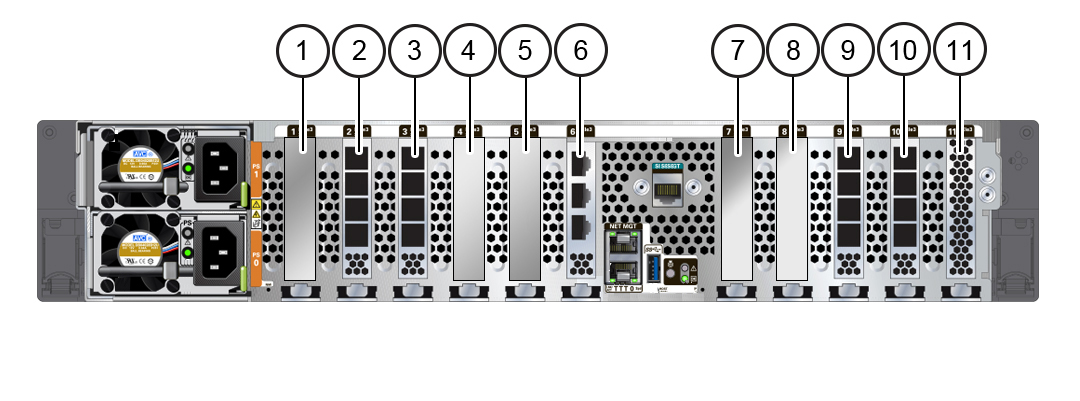
ZS7-2 PCIe Card Configuration
The 11 PCIe slots are located inside the controller at the back. As viewed from the back of the controller, the slots are divided into two groups, a group of six to the left of the built-in network ports and rear indicators and a group of five to the right side of the network ports and indicators. The PCIe slots are designated from left to right (back view) with the six slots on the left side designated as PCIe Slot 1 to PCIe Slot 6, and the five slots on the right side designated as PCIe Slot 7 to PCIe Slot 11. The following figure shows the ZS7-2 high-end model.

|
PCIe Slot Width and Capabilities
The controller contains 11 low-profile PCIe 3.0 card slots, which have the following width and capabilities:
-
Slot 1 has a x16 connector with x16 electrical interface
-
Slot 7 has a x16 connector with x8 electrical interface
-
Slots 2, 3, 4, 5, 6, 8, 9, 10 and 11 have x8 connectors (x8 electrical interface)
Note - While slot 7 can accommodate a x16 width card, the capability of the card will be limited by the x8 electrical interface.
PCIe Card Slot Population Order
Each base unit ZS7-2 is always loaded with the following HBAs or fillers:
-
Slot 2: 4x4 SAS-3 HBA
-
Slot 3: 4x4 SAS-3 HBA high-end model; filler panel mid-range model
-
Slot 6: Cluster interface card
-
Slot 9: 4x4 SAS-3 HBA high-end model; filler panel mid-range model
-
Slot 10: 4x4 SAS-3 HBA
-
Slot 11: Internal SAS-3 HBA
All allowable option ZS7-2 PCIe cards should be installed in the remaining card slot locations and filled in accordance to the following priority and sequence as follows:
-
Install optional dual port QDR InfiniBand (IB) cards into slot 4, then slot 8, then slot 5, then slot 7, then slot 1.
-
Install optional dual port 40GbE NIC cards into slot 4, then slot 8, then slot 5, then slot 7, then slot 1.
-
Install optional dual port 32Gb FC HBA cards into slot 4, then slot 8, then slot 5, then slot 7, then slot 1.
-
Install optional quad port 10GbE NIC cards into slot 4, then slot 8, then slot 5, then slot 7, then slot 1.
-
Install optional quad port 10GBASE-T NIC cards into slot 4, then slot 8, then slot 5, then slot 7, then slot 1.