ZS7-2 Internal Components
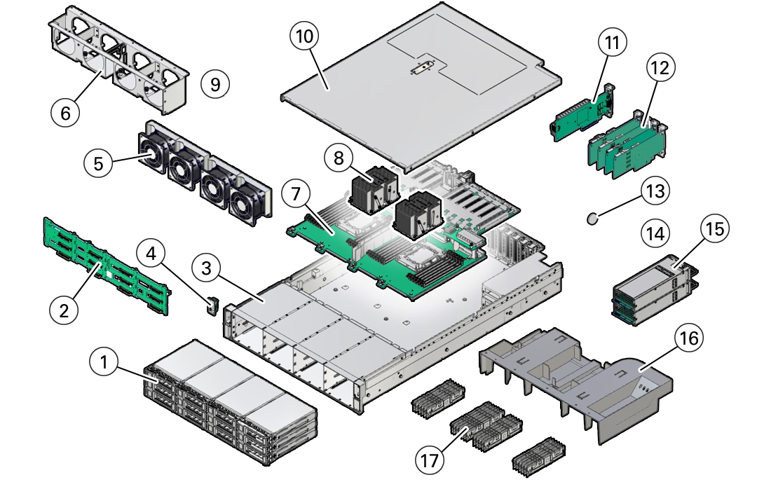
The major components of the ZS7-2 controller are shown in the following figure and
identified in the legend.
|
|
|
1
|
Two system disks, ten filler panels
|
|
2
|
Disk backplane
|
|
3
|
System chassis
|
|
4
|
Front LED indicator module and temperature sensor
|
|
5
|
Fan modules
|
|
6
|
Fan tray
|
|
7
|
Motherboard assembly
|
|
8
|
Processors and heatsinks
|
|
9
|
N/A
|
|
10
|
Top cover
|
|
11
|
Oracle Storage 12 Gb SAS PCIe HBA, internal
|
|
12
|
PCIe cards
|
|
13
|
System battery
|
|
14
|
N/A
|
|
15
|
Power supplies
|
|
16
|
Air baffle
|
|
17
|
DIMMs
|
|
ZS7-2 Storage Drive
This section shows the location and explains the functions of the storage drive
status indicators.

|
|
|
1
|
Ready to Remove (blue)
|
|
2
|
Service Action Required (amber)
|
|
3
|
OK/Activity (green)
|
|
ZS7-2 Fan Module
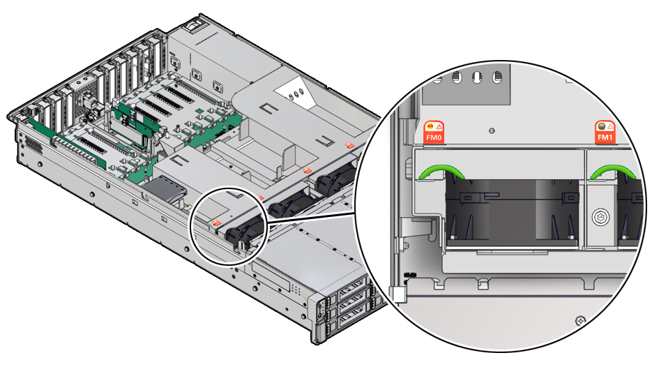
The four fan modules are located towards the front of the ZS7-2 controller between
the CPUs and the drive trays. The fan modules are designated from left to right. As
pictured in the following illustration, the four fan modules are designated as: FMO,
FM1, FM2, and FM3.
|
|
Amber – The fan module is faulty. The front Top Fan LED
and the front and back panel Fault-Service Required LEDs are
also lit if the system detects a fan module fault.
|
|
Not Illuminated – The fan module is operational
(OK).
|
|
ZS7-2 Power Supply
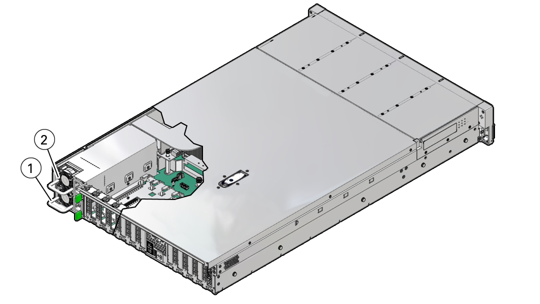
The two power supplies are located on the right side of the controller (from the
front of the controller) and are designated from top to bottom. The power supplies
are accessible from the back of the controller. As indicated in the following
drawing, the top designation is PS 1 and the bottom designation is PS 0.
|
|
|
1
|
Power supply 0
|
|
2
|
Power supply 1
|
|
The two power supplies ensure redundancy by allowing the controller to operate
when one of the power supplies fails. However, when the controller is operating on
one power supply, redundancy no longer exists, and the risk for an unexpected shut
down and a loss of data is high. When a power supply or any component that is part
of a redundant configuration fails, replace it immediately.
|
|
|
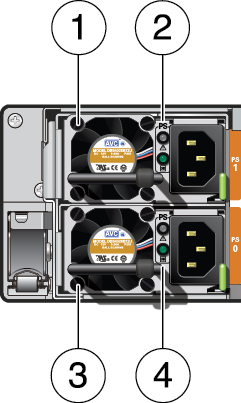
1
|
Power supply (PS) 1
|
|
2
|
PS 1 status indicators: Fault-Service Required LED: amber; AC
power input and DC power output OK LED: green
|
|
3
|
PS 0
|
|
4
|
PS 0 status indicators: Fault-Service Required LED: amber; AC
power input and DC power output OK LED: green
|
|
ZS7-2 DIMM
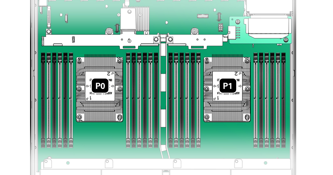
The physical layout of the DIMMs and processor(s) is shown in the following
figure. When viewing the controller from the front, processor 0 (P0) is on the
left.
Each processor, P0 and P1, has 12 DIMM slots organized into 6 memory channels.
Each memory channel contains two DIMM slots: a black DIMM slot (channel slot 0) and
a white DIMM slot (channel slot 1).
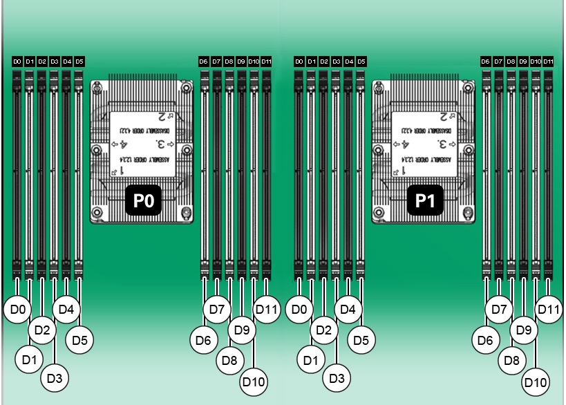
As shown in the
following figure, DIMM slots are labeled D0 through D5 to the left of each
processor, and D6 through D11 to the right of each processor. For each processor,
the black slots are: D0, D2, D4, D7, D9, and D11. Similarly, for each processor, the
white slots are: D1, D3, D5, D6, D8, and D10.
The following
table describes the supported memory configurations for Oracle ZFS Storage ZS7-2.
The mid-range model supports 8 or 16 DIMMs, and the high-end model supports 24
DIMMs. All DIMMs are 64 GB. The DIMM locations in the table apply to both P0 and P1
processors; for example, P0/D2,P0/D4,P0/D7,P0/D9 and
P1/D2,P1/D4,P1/D7,P1/D9.
|
|
|
|
|
|
Oracle Storage ZS7-2 mid-range model, low-memory
configuration
|
8
|
D2, D4, D7, D9
|
512 GB
|
Black sockets are populated
|
|
Oracle Storage ZS7-2 mid-range model, high-memory
configuration
|
16
|
D2, D4, D7, D9
D3, D5, D6, D8
|
1024 GB
|
Black sockets are populated
White sockets are populated
|
|
Oracle Storage ZS7-2 high-end model
|
24
|
D0, D2, D4, D7, D9, D11
D1, D3, D5, D6, D8, D10
|
1536 GB
|
Black sockets are populated
White sockets are populated
|
|
ZS7-2 Storage Drives
Only two of the storage drive slots are used for system boot purposes, which
include redundant mirrored drives. These are used and designated consecutively from
left,
bottom (System Disk 0) to
right
(System Disk 1). All other storage drive slots include filler panels as is indicated
in the following drawing. Drive slots are numbered from left to right, and from
bottom to top.

|
1 System Disk 0
|
2 System Disk 1
|
3 Filler panel
|
|
4 Filler panel
|
5 Filler panel
|
6 Filler panel
|
|
7 Filler panel
|
8 Filler panel
|
9 Filler panel
|
|
10 Filler panel
|
11 Filler panel
|
12 Filler panel
|
|


