Replacing a 7x20 DIMM
 | Caution - This procedure requires that you handle components that are sensitive to static discharge, which can cause the component to fail. To avoid damage, wear an antistatic wrist strap and use an antistatic mat when handling components. |
To identify a specific memory module that has faulted, you must open the
storage controller and use the amber status LEDs on the motherboard. To identify
a general memory fault, go to the Maintenance > Hardware screen of the BUI,
and click on the right-arrow icon  on the controller. Then click DIMMs to locate the faulted
component, indicated by the warning icon
  .
.
- Power off the storage controller as described in Powering Off the Controller.
-
Disconnect the AC power cords from the rear panel of the storage
controller.

Caution - Because 3.3 VDC standby power is always present in the system, you must unplug the power cords before accessing any cold-serviceable components.
- Extend the controller from the rack as described in Extending the Controller from the Rack.
-
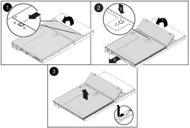
7120 or 7320: Components may differ
slightly between the 7120 and 7320, however service procedures for each are
identical. The illustration shows the 7320 controller. To remove the top
cover:
- Unlatch the fan module door, pull the two release tabs back, rotate the fan door to the open position and hold it there.
- Press the top cover release button and slide the top cover to the rear about a half-inch (1.3 cm).
- Lift up and remove the top cover.
-
Also remove the air baffle by pressing the air baffle connectors outward
and lifting the air baffle up and out of the controller.
-
7420: To remove the top cover:
-
Simultaneously lift both cover latches in an upward motion.
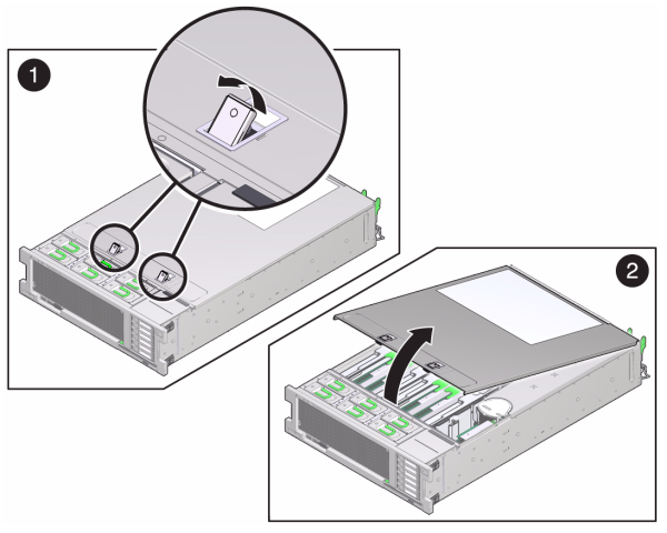
- Lift up and remove the top cover.
-
Simultaneously lift both cover latches in an upward motion.
-
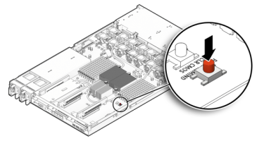
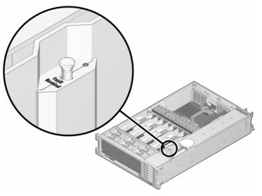
To locate the DIMM you want to service, press the Fault Remind Button on
the storage controller.
The following illustration shows the Fault remind button on the 7120 controller.
The following illustration shows the Fault remind button on the 7420 controller.
-
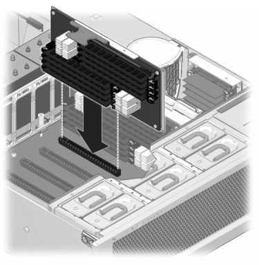
7420: Identify the memory riser that
hosts the faulted DIMM by the Service Required status indicator. Lift the
memory riser straight up to remove it from the motherboard, and place it on
an antistatic mat.
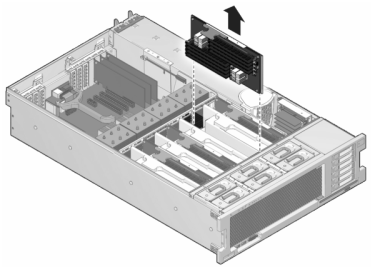
-
Rotate both DIMM slot ejectors outward as far as they will go and
carefully lift the faulted DIMM straight up to remove it from the
socket.
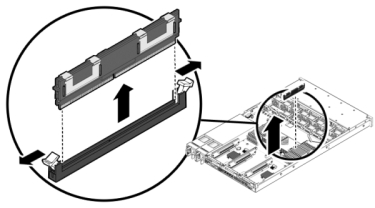
-
Line up the replacement DIMM with the connector, aligning the notch with
the key to ensure that the component is oriented correctly.
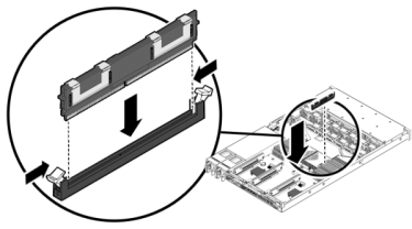
- Push the DIMM into the connector until the ejector tabs lock the component in place.
-
7120 or 7320: Components may differ
slightly between the 7120 and 7320, however service procedures for each are
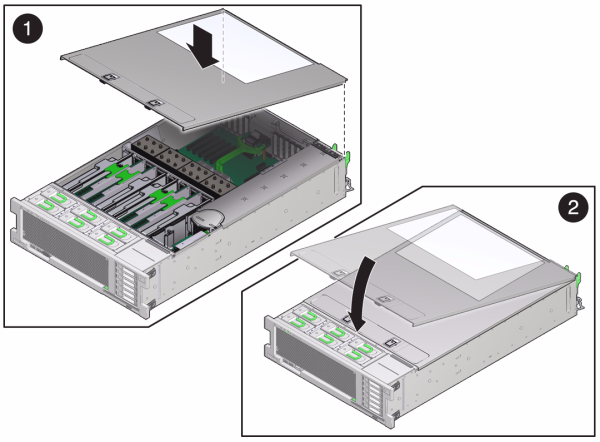
identical. The illustration shows the 7320. To replace the cover:
- Place the top cover on the chassis so that it hangs over the rear of the storage controller by about an inch (2.5 cm).
- Slide the top cover forward until it seats.
-
Close the fan cover and engage the fan cover latches. The cover
must be completely closed for the storage controller to power
on.
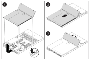
-
7420: To replace the cover:
-
Push the memory riser module into the associated CPU memory riser
slot until the riser module locks in place.
- Place the top cover on the chassis so that it is forward of the rear of the storage controller by about an inch (2.5 cm).
-
Slide the top cover toward the rear of the chassis until it seats
and press down on the cover with both hands until both latches
engage.
-
Push the memory riser module into the associated CPU memory riser
slot until the riser module locks in place.
-
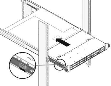
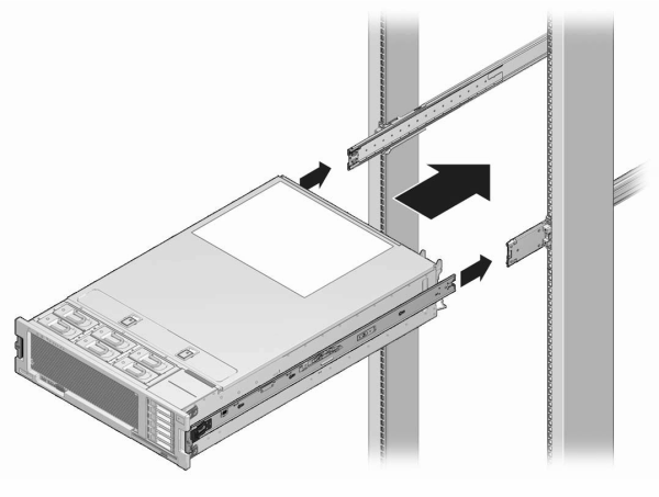
Push the release tabs on the side of each rail and slowly push the storage
controller into the rack.
The following image shows the 7420 chassis.
- Reconnect all cables to their original ports, referring to the labels previously added as a guide. For cabling details, see the Oracle ZFS Storage Appliance Cabling Guide .
- Connect the power cords to the power supplies.
- Verify that standby power is on, indicated by the Power/OK status indicator flashing on the front panel about two minutes after the power cords are plugged in.
-
Use a pen or other pointed object to press and release the recessed Power
button on the storage controller front panel.
The Power/OK status indicator next to the Power button lights and remains lit.
-
Go to the Maintenance > Hardware screen of the BUI. Click the
right-arrow icon
 for the controller and then click DIMM to verify that
the online icon
  is green for the newly installed DIMM.
- If a fault does not self-clear, see Repairing Active Problems.