ZS5-4 CPUs and Memory Riser Card
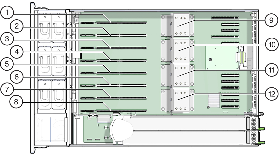
The four CPU sockets are located in the middle of the controller and are designated consecutively from right to left (from the front of the controller). The rightmost socket is CPU-0 and is designated as P0, and the leftmost socket is CPU-3, designated as P3.
The eight memory riser (MR) card slots are located between the fan module slots and the CPU sockets. Consecutively from right to left, the rightmost slot is slot 0, and the leftmost slot is slot 7.
The slots are also designated by their association with the four CPU sockets (P0-P3). Two slots are assigned to each CPU socket. For example, slots 0 and 1 are paired with CPU socket, P0, and are designated as P0/MR0 and P0/MR1. Slots 2 and 3 are paired with CPU socket, P1 and are designated as P1/MR0 and P1/MR1. This numbering pattern continues for the remaining slots.

|
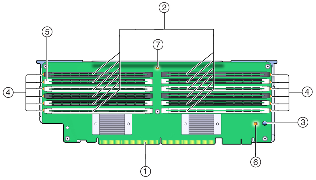
Memory Riser Card Components
The following illustration shows the components of the memory riser card.

|
Memory Riser Cards Physical Layout
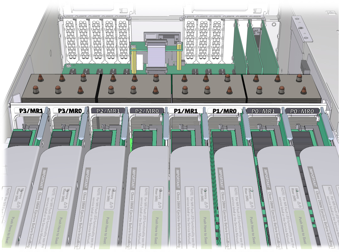
The memory riser cards are located behind the fan module bay. The designations each memory riser (MR) card and its associated CPU are located inside the controller on labels affixed to the rear MR card bracket. The cards are designated as MR, and the CPUs are designated as P. The slots and CPUs are labeled from right to left when viewed from the front of the controller as follows:
Note - Each CPU has two assigned card slots (MR0 and MR1).
P0/MR0 (rightmost slot)
P0/MR1
P1/MR0
P1/MR1
P2/MR0
P2/MR1
P3/MR0
P3/MR1 (leftmost slot)
The following illustration shows the numbering for the memory riser slots and their associated CPUs as described above:

Memory Riser Card Population Rules
The memory riser population rules for the controller are as follows:
Each CPU has two dedicated memory riser card slots (MR0 and MR1).
The dedicated memory riser slots for each installed CPU must contain a memory riser card. A four CPU system must contain eight memory riser cards.
When populating the controller with memory riser cards:
First populate riser slot MR0 for each CPU, starting with the lowest numbered CPU (P0).
Then populate riser slot MR1 for each CPU, starting with the lowest numbered CPU (P0).