ZS4-4 Front and Rear Panel Components
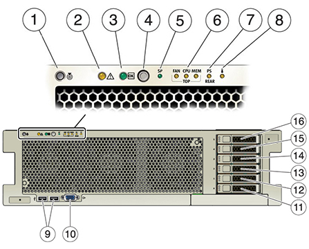
Front Panel Components - The ZS4-4 controller drive slots and front panel components are shown in the following figure.
Figure 13 ZS4-4 Controller Front Panel

|
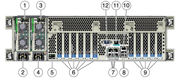
Rear Panel Components - The ZS4-4 rear panel is shown in the following figure. Base configuration PCIe cards are not depicted in this illustration.
Figure 14 ZS4-4 Controller Rear Panel

|
Cluster Interface Card Compatibility - The ZS4-4 controller can contain a Version 2 or Version 3 cluster interface card. For clustered controllers, ensure you are using the same version in each controller because these two versions are not compatible.
For information about how to connect cables to form a cluster, see Connecting Cluster Cables in Oracle ZFS Storage Appliance Cabling Guide.
Ethernet Ports
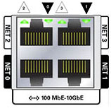
The ZS4-4 has four RJ-45 10-Gigabit Ethernet (10GbE) network connectors on the rear panel, labeled NET 0, NET 1, NET 2, and NET 3 (bottom left to top right), as shown in the figure below. Use these ports to connect the appliance to the network.
The LEDs located above the NET ports, labeled 2, 0, 3, 1 (left to right) are Link/Activity indicators.
|
Note - Speed is not indicated for the NET ports.
Figure 15 ZS4-4 Ethernet Ports

Network Management Port
The network management connector (NET MGT), shown in the figure below, is an RJ-45 10/100/1000 BASE-T Ethernet port and provides an alternate terminal interface to the service processor (SP) console.
Figure 16 ZS4-4 Network Management Port

Serial Management Port
The serial management connector (SER MGT), shown in the figure below, is an RJ-45 port and provides a terminal connection to the SP console.
Figure 17 ZS4-4 Serial Management Port

4x4 SAS HBA
The 4x4 SAS HBA provides connectivity to external disk shelves. The HBA logical ports are numbered 3-0, top to bottom, as shown in the following figure.
Figure 18 4x4 SAS HBA Port Numbers
