7320 Front and Back Panel Components
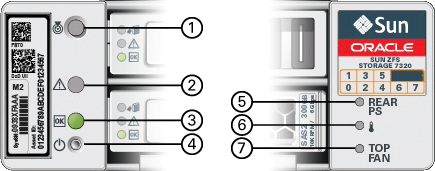
7320 Front Panel Components - The following figure and legend identify the front panel LEDs.
Figure 57 7320 Controller Front Panel LEDs

|
The following figure and legend identify the 7320 front panel drive locations. Two mirrored hard disk drives (HDDs) that store the operating system reside in slots 0 and 1. Up to four read-optimized cache solid state drives (SSDs) fill slots 2 through 5, in order. Slots 6 and 7 are empty and must contain drive fillers.
Figure 58 7320 Controller Front Panel Drive Locations

|
7320 Back Panel Components - Following is an illustration of the 7320 storage controller rear panel. The Sun 375-3609 belongs in slot 2, cannot be installed in any other slots, and a second is not offered as an option.
Figure 59 7320 Controller Rear Panel

|
Cluster Interface Card Compatibility - The 7320 controller contains a Version 2 cluster interface card. This card cannot be replaced with a Version 3 cluster interface card.
For information about how to connect cables to form a cluster, see Connecting Cluster Cables in Oracle ZFS Storage Appliance Cabling Guide.
Ethernet Ports
There are four RJ-45 Gigabit Ethernet connectors (NET0, NET1, NET2, NET3) located on the motherboard that operate at 10/100/1000 Mbit/sec. These network interfaces must be configured before use.
Network Management Port
The network management connector (NET MGT) is an RJ-45 10/100 BASE-T Ethernet port on the motherboard and provides an alternate terminal interface to the SP console.
Figure 60 7320 Controller Network Management Port

Serial Management Port
The serial management connector (SERIAL MGT) is an RJ-45 connector and is a terminal connection to the SP console.
Figure 61 7320 Controller Serial Management Port
