Replacing a ZS5-4 Memory Riser Card
Use the following procedure to replace a ZS5-4 memory riser card.
- Shut down the controller using one of the power-off methods described in Powering Off the Controller.
-
Disconnect the AC power cords from the rear panel of the storage
controller.

Caution - Because 3.3 VDC standby power is always present in the system, you must unplug the power cords before accessing any cold-serviceable components.
- Extend the controller from the rack as described in Extending the Storage Controller from the Rack.
- Remove the top cover as described in Removing the Top Cover.
-
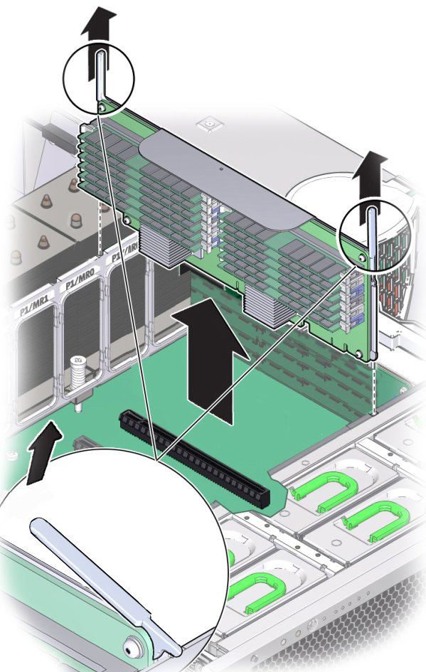
To remove the memory riser card, pull the handles upward to disengage the
connector from the motherboard, and carefully lift the memory riser straight
up and out of the controller.

The memory riser card is designed to fit tightly into the memory riser connector on the motherboard. The handles on the memory riser card provide leverage against the chassis to disengage the card's edge connector from the connector on the motherboard.
-
On the replacement memory riser card, ensure that all populated and
unpopulated DIMM slot ejector levers are in the closed and locked
position.

Caution - Open DIMM ejector levers can break off during the installation of the memory riser card. All populated and unpopulated DIMM slot ejector levers on the memory riser card must be in the fully closed and locked position before installing the card in the controller.
-
Ensure that all populated and unpopulated DIMM slot ejector levers are in
the closed and locked position.

Caution - The ejector levers are only used to remove a memory riser card and are not used to install a card.
-
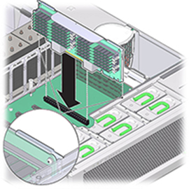
Position the memory riser card over the slot on the motherboard.
The DIMMs on the card must face to the left (when positioned at the front of the controller).
-
Lower the memory riser card into the controller and set it on the slot on
the motherboard.

- Ensure that the memory riser card connector is aligned with the slot.
- Firmly push down on the metal bracket on top of the card, to seat the card within the connector on the motherboard.
- Replace the top cover on the chassis.
- Return the controller to the normal rack position by pushing the release tabs on the side of each rail while slowly pushing the storage controller into the rack.
- Reconnect all cables to their original ports, referring to the labels previously added as a guide. For cabling details, see the Oracle ZFS Storage Appliance Cabling Guide.
- Reconnect the power cords to the power supplies.
- Verify that standby power is on, indicated by the Power/OK status indicator flashing on the front panel about two minutes after the power cords are plugged in.
- Press and release the recessed Power button on the storage controller front panel.
-
Go to the Maintenance > Hardware screen of the BUI. Click the
right-arrow icon for the controller and then click DIMM to verify that the
status icon
 is green for the newly installed memory riser
card.
- If a fault does not self-clear, see Repairing Active Problems.