Oracle Storage Drive Enclosure DE3-24
This section introduces the front and rear panel components of the DE3-24P and DE3-24C disk shelves.
DE3-24P Disk Shelf
The Oracle Storage Drive Enclosure DE3-24P is a 2U chassis that supports 24 2.5'' SAS-3 drives. The high-performance HDDs provide reliable storage, and the SSDs provide accelerated write operations. This disk shelf features dual, redundant I/O Modules (IOMs), and dual power supply with fan modules.
Figure 75 DE3-24P Drive Locations (Front View)

Up to four write-optimized log SSDs are supported per disk shelf. Log devices should be populated in order of slots 20, 21, 22, and 23.
External Read Cache Devices - Read cache devices, installed in DE3-24 disk shelves, are external to the controller and referred to as external second level adaptive replacement cache (EL2ARC). When a cluster takeover occurs, read cache remains persistent and sharable between controllers, enabling read performance to be sustained. For slot configuration details and minimum software requirements, see Disk Shelf Configurations.
Figure 76 DE3-24P Status Indicators (Front View)
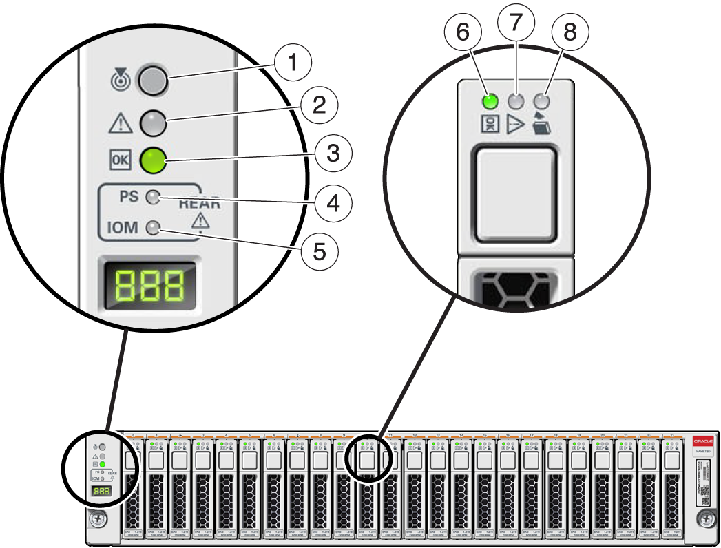
| ||||||||||||
Figure 77 DE3-24P Rear Panel

| ||||||
DE3-24C Disk Shelf
The Oracle Storage Drive Enclosure DE3-24C is a 4U chassis that supports 24 3.5" SAS-3 drives. The SSDs provide accelerated write operations, and the high-capacity HDDs provide reliable storage. This disk shelf features dual, redundant I/O Modules (IOMs), and dual power supply with fan modules.
Figure 78 DE3-24C Drive Locations (Front View)
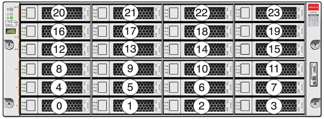
Up to four write-optimized log SSDs are supported per disk shelf. Log devices should be populated in order of slots 20, 21, 22, and 23.
External Read Cache Devices - Read cache devices, installed in DE3-24 disk shelves, are external to the controller and referred to as external second level adaptive replacement cache (EL2ARC). When a cluster takeover occurs, read cache remains persistent and sharable between controllers, enabling read performance to be sustained. For slot configuration details and minimum software requirements, see Disk Shelf Configurations.
Figure 79 DE3-24C Status Indicators (Front View)
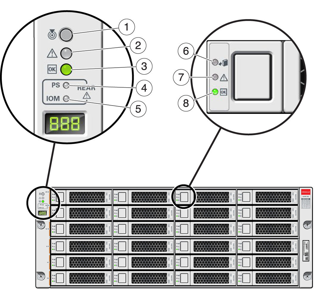
| ||||||||||||
Figure 80 DE3-24C Rear Panel
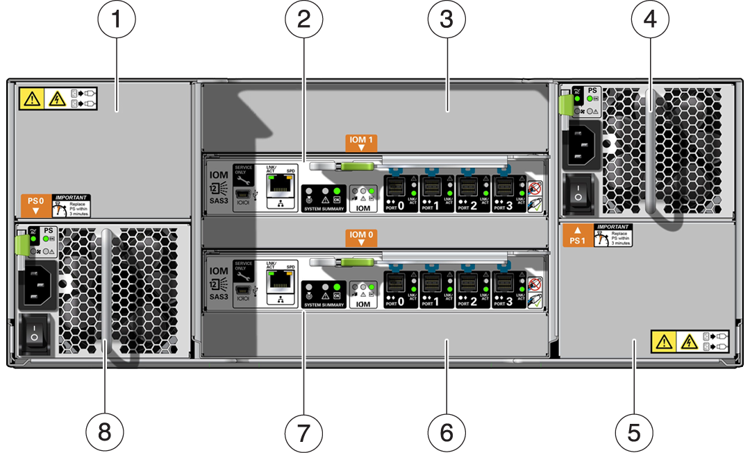
| ||||||||||||
Note - It is especially important that power supplies and their filler panels are in the correct slots.
Figure 81 DE3 I/O Module Indicators
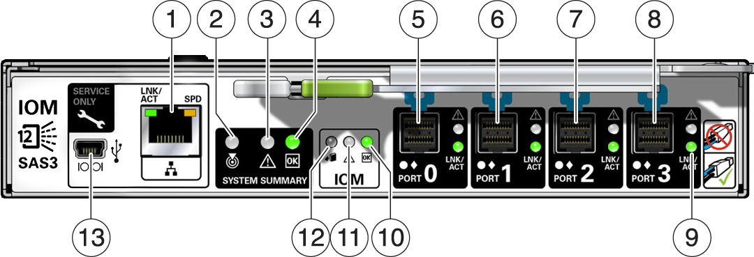
| ||||||||||||||||||
The DE3-24C and DE3-24P disk shelves use the same I/O Module.
Figure 82 DE3 Power Supply Indicators
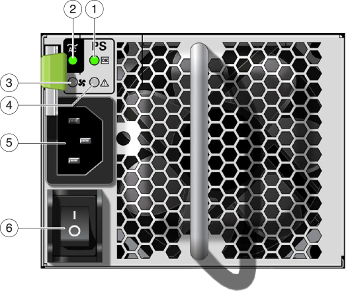
| |||||||||
The DE3-24C and DE3-24P disk shelves use the same power supply.