ZS4-4 Internal Components
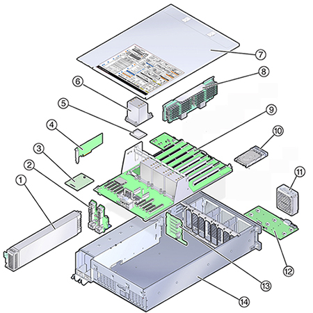
The ZS4-4 chassis contains both customer-replaceable units (CRUs) and field-replaceable units (FRUs) as shown in the following figure. FRUs must be replaced by trained Oracle service technicians.
Figure 20 Internal Components (Exploded View)

|
ZS4-4 System Drive - The ZS4-4 controller has two system boot drives in slots 0 and 1, configured as a mirrored pair. Read-optimized cache devices can be installed in controller slots 2 through 5, or installed in disk shelf slots 20 through 23.
Note - Read cache devices must be installed in either the controller or a disk shelf. Read cache devices cannot be installed in both controller and disk shelf slots at the same time. For software requirements and slot configuration rules, see Disk Shelf Configurations.
A filler panel must be installed in empty drive slots. The system drive LEDs are shown in the following figure.
Figure 21 System Drive LEDs

For information about supported disks and capacities, refer to the Oracle Systems Handbook.
|
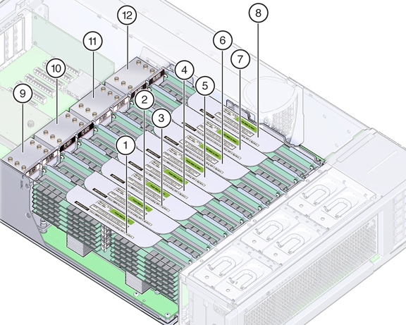
ZS4-4 CPU and Memory - The ZS4-4 controller has four Intel Xeon E7-8895 v2 15-core 2.8 GHz CPUs and eight memory riser cards as shown in the following figure. The memory configuration is 16GB DDR3 DIMMs to accommodate up to 1.5TB (ninety-six 16GB). All ZS4-4 DIMM risers are fully populated to accommodate this offering.
Figure 22 ZS4-4 CPU and Memory

|
Each memory riser card contains twelve DIMM slots, four DDR3 channels, and two memory buffer ASICs. Each each memory buffer has two channels (A and B) and links to three DIMM slots per channel. Each memory buffer is connected to the processor's built-in memory controller by an SMI-2 link.
DIMM names in appliance logs and the Maintenance > Hardware view are displayed with the full name, such as /SYS/MB/P0/D7.
For more information about memory layout and procedures for replacing DIMMs, see Replacing a ZS4-4 DIMM.
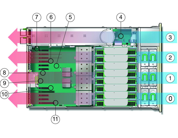
ZS4-4 Cooling Subsystem - The ZS4-4 internal components are cooled by air that is pulled in through the front of the controller and exhausted out the back of the controller. Cooling occurs in two areas of the chassis: the power supply area and the motherboard area.
The following figure shows the cooling zones and the approximate location of the temperature sensors. The accompanying legend table provides sensor NAC names and sensor motherboard designations.
Figure 23 ZS4-4 Cooling Subsysem

|