Connect the PDU Power Cords
Note - If you are installing a stand-alone SPARC M8-8 or SPARC M7-8 server into your own rack, see Prepare the Stand-Alone Server Power Cords for instructions on preparing the server power cords.
 | Caution - Your site must have a local power disconnect (for example, circuit breakers) between the power source and the power cords. Ensure that these circuit breakers are set to off before connecting the power cords. |
 | Caution - Ensure that you install the server near your power grid's electrical outlets, and ensure that these outlets are easily accessible in case you must detach the power cords in an emergency. |
The server receives power from six PDU power cords. The server is designed to receive power from two separate power grids, with three PDU power cords receiving power from one power grid and the remaining three PDU power cords receiving power from a second power grid. You must connect all six PDU power cords.
Note - To aid installing and servicing the PDU power cords, label both ends of the cords with the PDU letter and the cord number (PDUA-0, PDUA-1, PDUA-2, PDUB-0, and so on) or with a number specific to your facility. When facing the rear of the server, PDU-A is at the left side and PDU-B is at the right side.
Note - To maintain the ability to hot service the PDUs, route and secure all PDU power cords and data cables within the rack to enable the PDUs to be removed from the rear of the rack. Route and secure these cables so that the PDUs can be replaced without removing the side panels of the rack.
-
Prepare to connect the PDU power cords:
-
Review the PDU Power Cord Specifications and Facility Power Receptacles to ensure that you received the correct power cords for your facility.
-
Review the Understanding Power Cord-to-PDU Relationships to understand which power cord supplies power to which power supply.
-
Review the Facility Power Requirements.
-
Review the Circuit Breaker Capacity Requirements to ensure that the circuit breakers accommodate your facility power infrastructure.
-
-
Confirm that all facility circuit breakers are set to the OFF
position.
Consult with your facilities manager or a qualified electrician for the specific instructions on how to use the circuit breakers at your data center.
- Open the rear door and attach an antistatic wrist strap.
-
Determine the rack type.
Note - Each side of an Oracle Rack Cabinet 1242 has two panels. If you see a seam between the two side panels, your server shipped in an Oracle Rack Cabinet 1242.- If the server shipped in a Sun Rack II 1242, skip to Step 8.
- If the server shipped in an Oracle Rack Cabinet 1242, continue to the next step.
-
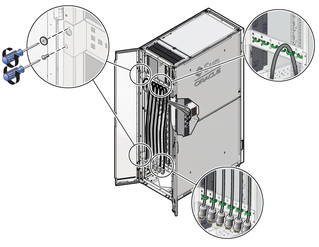
On Oracle Rack Cabinet 1242, open the Velcro straps securing the PDU power
cords to the shipping brackets.
-
Use a T25 Torx wrench key to remove the screws securing the two shipping
brackets to the rack.
Remove the shipping brackets.
- Skip to Step 10.
-
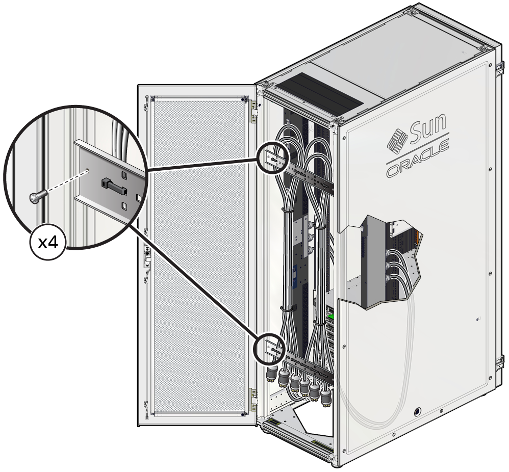
On a Sun Rack II 1242, use a box cutter to cut the tie-wraps securing the
PDU power cords to the shipping brackets.
-
Use a T25 Torx wrench key to remove the screws securing the two shipping
brackets to the rack.
Remove the shipping brackets.
-
Confirm that all PDU circuit breakers are switched off.
Ensure that both PDUs are turned completely off.
When facing the rear of the server, PDU-A is at the left side and PDU-B is at the right side. Each PDU has nine circuit breakers, one for each socket group.
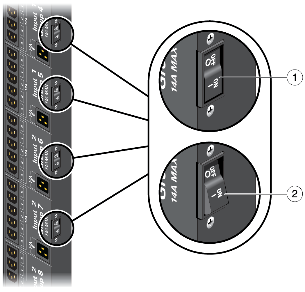 No.Description1Circuit breaker switch lies flat in the On position.2Circuit breaker switch is tilted in the Off position.
 -
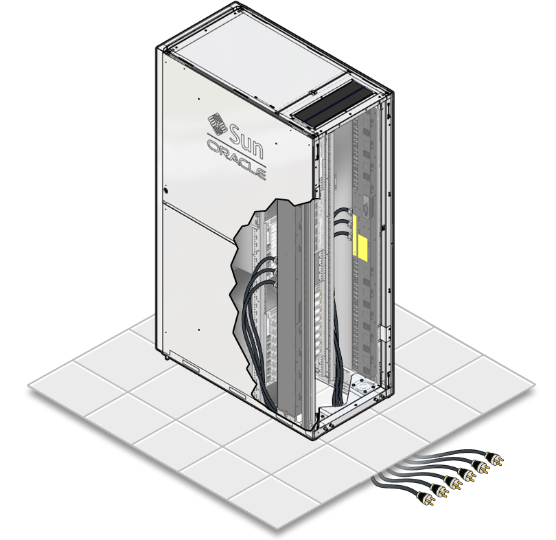
Route the power cords to the facility receptacles either up through the
top of the rack or below the flooring.
When routing the PDU power cord up, route the cord out through the top cable-routing window.
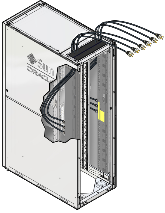
When routing the PDU power cord down, route the cord down through the floor opening.
-
Connect the PDU power cord connectors into the facility AC receptacles.
Consult with your facilities manager or a qualified electrician for the specific instructions on how to connect the power cords at your data center.
-
Label both ends of the PDU power cords, the facility AC receptacles, and
the facility circuit breakers with the PDU letter number and cord number
(PDUA-0, PDUA-1, and so on) or with a unique facility number.
By labeling these components, you will be able to return the power cords to the appropriate outlets after servicing the server.
Note - If you have labeled these components using a numbering sequence unique to your facility, ensure that you can still determine which PDU power cord is associated with each facility receptacle and circuit breaker.