Install and Secure the Server
 | Caution - You must use a mechanical lift that can support 1000 lbs (454 kg) when installing the server into a rack. Do not attempt to lift the server into a rack without a mechanical lift. The combined weight of a SPARC M8-8 server and inner pallet is around 459 lbs (208.2 kg), and the weight of a SPARC M7-8 server and inner pallet is around 439 lbs (199.1 kg). |
- Ensure that the mechanical lift is level and stable.
-
Lift the server up so that it is around 0.2 in (5 mm) above the surface of the
shelf rails.
Ensure that the edge of the mechanical lift's tray is as close to the front of the rack as possible. If you lifted the server on its inner pallet, ensure that the edge of the pallet is as close to the rack as possible.
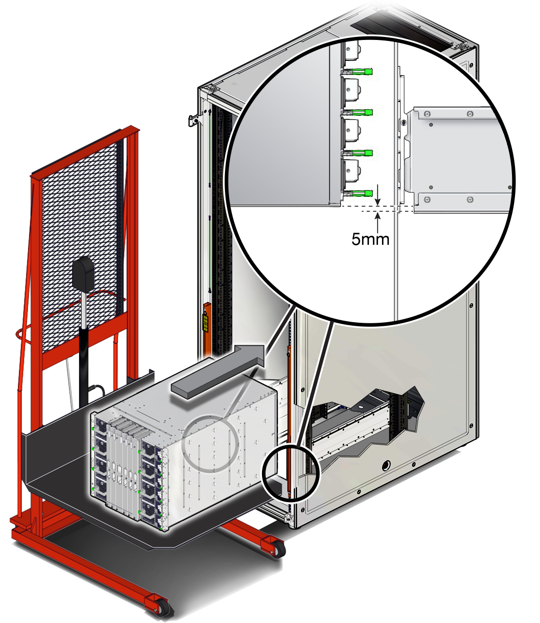
-
Carefully install the server into the front of the rack.

Caution - Always push the server directly into the rack. Never rock the server back and forth into the rack.

Caution - To reduce the risk of personal injury, never reach or walk under the server while it is raised on a mechanical lift.
-
Slide the server a quarter of the way into the rack.

Caution - Always push the server at the sides of the chassis. Never push on the front interconnects.
Ensure that the bottom edge of the server clears the bottom of the rack rails.
- Lower the server slightly to where its weight is borne evenly between the slide rails and the pan of the mechanical lift.
- Slide the server until it is three-quarters of the way into the rack.
- Lower the mechanical lift pan slightly so that the weight of the server is borne entirely by the slide rails.
- Push the server the rest of the way into the rack.
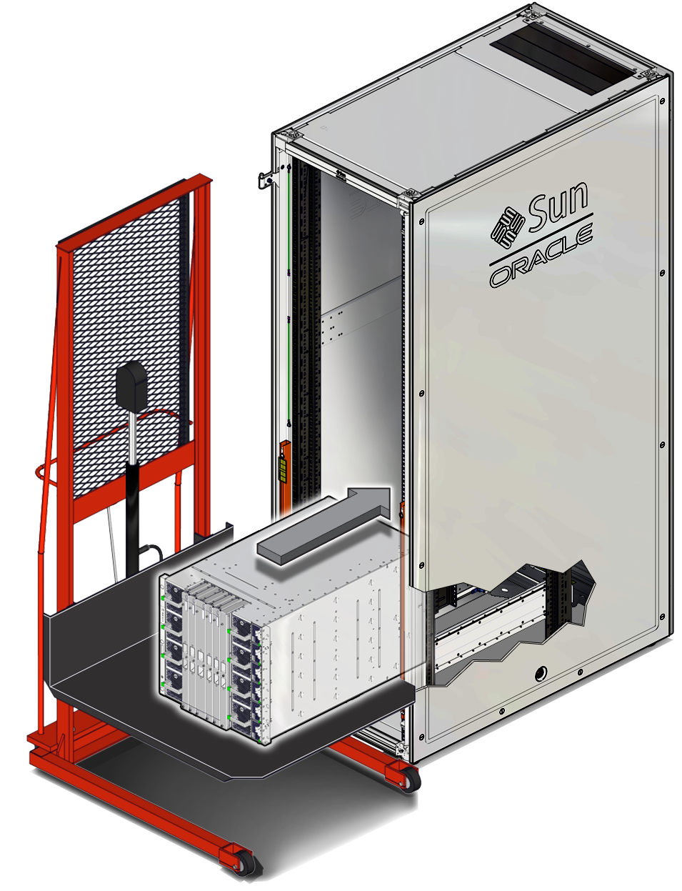
-
Slide the server a quarter of the way into the rack.
-
If the rear of the server stops at the rear mounting bracket, follow these
steps to push the server the rest of the way into the rack.
-
Using a T30 Torx screwdriver, remove the two top screws of the lower
rear bracket and loosen the remaining four screws. Slide the lower rear
bracket down and then securely tighten the lower four screws.
The lower rear bracket should now be around 0.01 in. (2 mm) below the surface of the shelf rails.
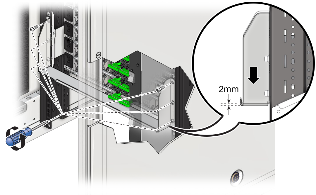
- Push the server the rest of the way into the rack.
-
Using a T30 Torx screwdriver, loosen the four screws on the lower rear
bracket and slide the bracket up against the chassis. Securely tighten
the top screws on each side of the lower rear bracket, and then securely
tighten the remaining four screws.
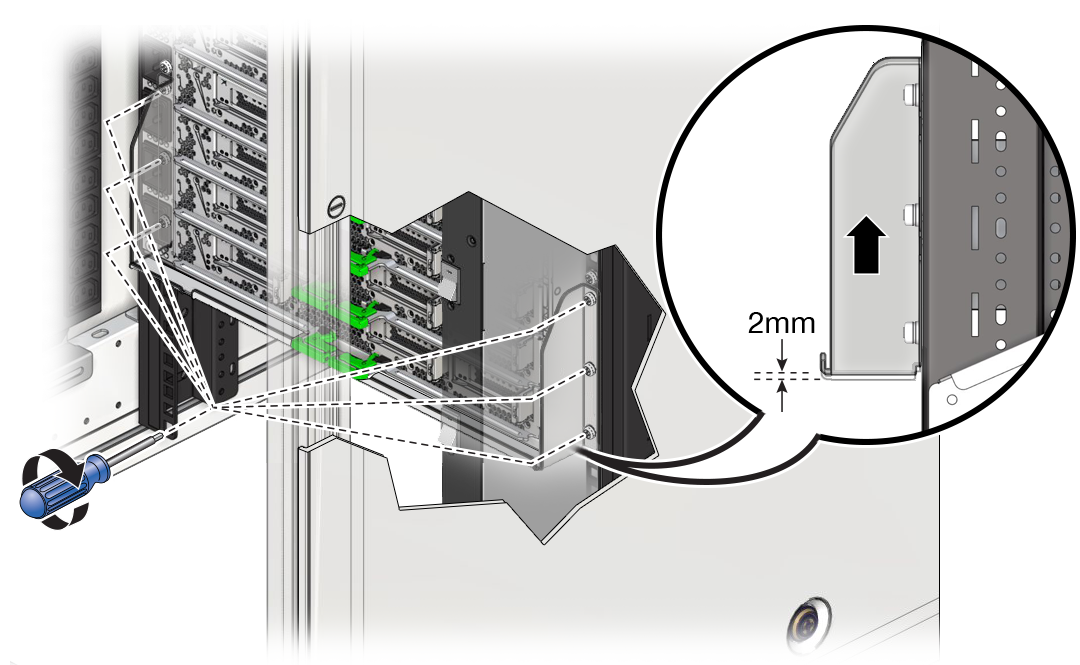
-
Using a T30 Torx screwdriver, remove the two top screws of the lower
rear bracket and loosen the remaining four screws. Slide the lower rear
bracket down and then securely tighten the lower four screws.
-
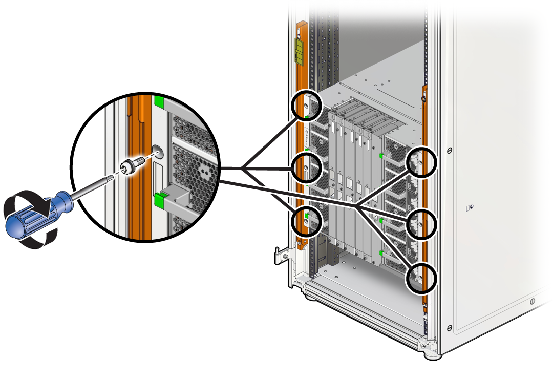
Using a T30 Torx screwdriver, secure the server front panel to the rack using
six M6 screws (three per side).
-
Repeat the following steps to install the left and right rear braces.
-
Place a rear brace on the top rear corner of the server and align it
with the rear RETMA rail.
Note - The rear braces are labeled "TOP LEFT" and "TOP RIGHT" as viewed from the rear of the rack.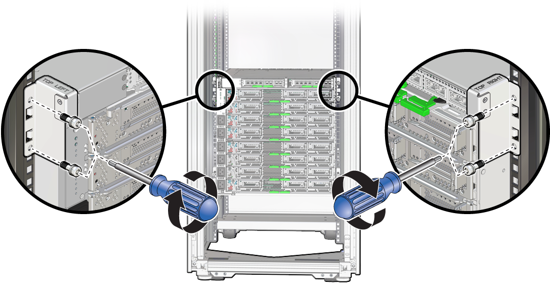
-
Using a T30 Torx screwdriver, secure the rear brace to the rail using
two M6 screws.
Note - Before tightening the screws, slide the top rear brackets down until they contact the top surface of the chassis.
-
Place a rear brace on the top rear corner of the server and align it
with the rear RETMA rail.
-
If you ordered optional hardware like PCIe cards, install them in the
server.
Refer to Optional Component Installation and Servicing PCIe Cards in SPARC M8 and SPARC M7 Servers Service Manual for more information.
- Continue the installation by preparing the server power cords.