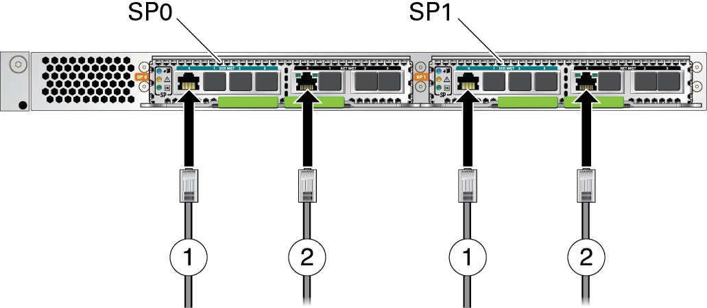
Connect SP Cables
You must connect serial and network cables to both SPs.
-
Locate the two SPs at the rear of the server.
-
On the SPARC M8-8 and SPARC M7-8 servers, the two SPs are located at the top of the server. See SPARC M8-8 and SPARC M7-8 Server Rear Components (Installation).
-
On a SPARC M7-16 server, the two SPs are located at the top of the switch chassis. See SPARC M7-16 Server Rear Components (Installation).
-
-
Connect Category 5 (or better) cables from the SP0 and SP1 SER MGT 0 ports
to separate terminal devices.
Connecting each serial cable to different terminal devices provides redundancy in case one terminal device fails.
Note - Each SP has four SER MGT ports, labeled 0 to 3. Connect the serial cables to the SER MGT port 0 on each SP. Unused ports are blocked by port covers. No.Description1Attach serial cables to the SP SER MGT 0 ports.2Attach network cables to the SP NET MGT 0 ports.
 -
Connect Category 6 (or better) cables from the SP0 and SP1 NET MGT 0 RJ-45
ports to separate network switches or hubs.
To achieve 1-GbE network speeds, use Category 6 (or better) cables and network devices that support 1000BASE-T networks. These 10/100/1000 Mbps NET MGT ports will autonegotiate to the speed of your network.
Note - Each SP has four NET MGT ports, labeled 0 to 3. Connect the network cables to the NET MGT port 0 on each SP. On SPARC M7-16 servers, some of these NET MGT ports will be cabled to SPPs in the server. Unused ports are blocked by port covers.