Install the Motherboard
Note - When replacing the motherboard, remove the SP and System Configuration PROM from the old motherboard and install these components on the new motherboard. The SP contains the Oracle ILOM system configuration data, and the System Configuration PROM contains the system host ID and MAC address. Transferring these components preserves the system-specific information stored on these modules. Whenever you replace the motherboard or the SP, you must update the firmware so the portions of firmware in the SP and on the motherboard are consistent.
- Unpack
the replacement motherboard and place it on an antistatic mat.
Note - On the 1-processor motherboard, do not remove the protective covering on the unused processor and memory riser areas. - Grasp the motherboard by the
handle and place it into the chassis.
Ensure that remaining cables do not get caught on edges of the motherboard.
Set the motherboard towards the front of the chassis, then slide it toward the rear of the chassis.
- Tighten the captive screw (in the corner near the fans) that secures the motherboard to the chassis.
- Reinsert and tighten the four
bus bar screws that secure the motherboard to the PS backplane.
Using a No. 2 screwdriver, tighten the bus bar screws until the PS backplane and the motherboard securely fasten to the bus bars.
- Replace the PS backplane
cover (panel 3).
- Align the PS
backplane cover.
Ensure that the tooth at the bottom of the cover is clear of the power supply cage.
You must guide two slots on the PS backplane cover around two pins on the inside of the power supply cage.
- Fit the two slots on the cover around the two pins.
- Lift up the cover a little to guide the two pins into the other part of the slots.
- Attach the screw to fasten the PS backplane cover in place.
- Align the PS
backplane cover.
- Push the power supplies back into place.
- Reattach all cables to the motherboard.
- In the center rear of the motherboard, connect the fan board power cable and the ribbon cable to the motherboard.
- Near the drives, connect two
shorter cables to the motherboard.
One cable goes to the drive backplane. The other is a ribbon cable to the power supply.
- Near the drives, connect two longer cables between the motherboard and the drive backplane.
- Reinstall the System Remind button
assembly (air divider) by sliding it into the chassis.

Caution - After replacing the motherboard, inspect the gasket on the air divider before installing the air divider securely. This dividing wall maintains a pressurized seal between the server cooling zones. Without this pressurized seal, the power supply fans will not be able to draw enough air to cool the drives properly.
- Reconnect all cables from the PS backplane, drive backplane, and fan board to their original locations on the motherboard.
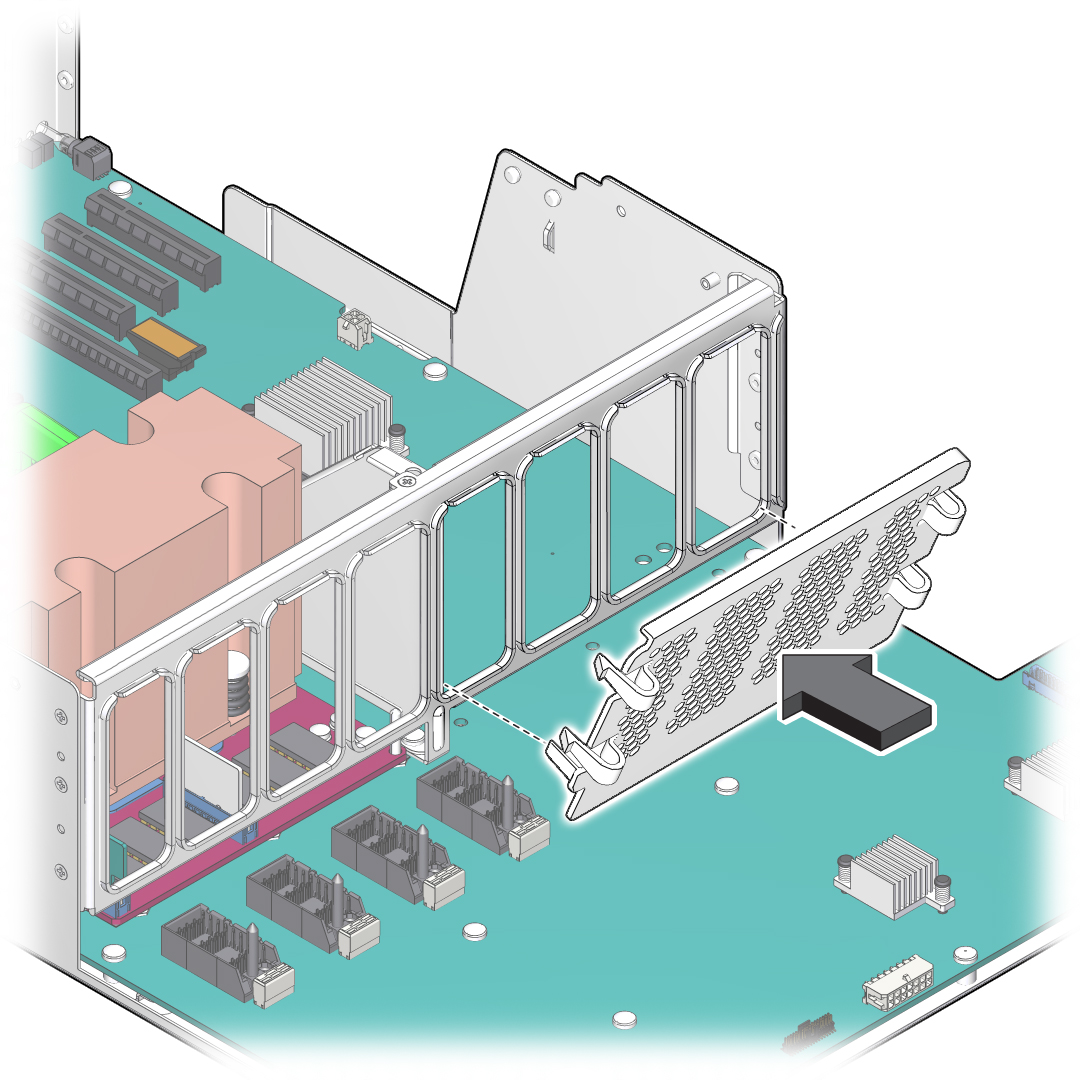
- On a 1-processor motherboard,
attach the airflow baffle to the empty side of the center bracket.
Note - Use the airflow baffle that you saved from the old 1-processor motherboard.- On the memory riser
side of the center bracket, align the airflow baffle over the four
unused slots.
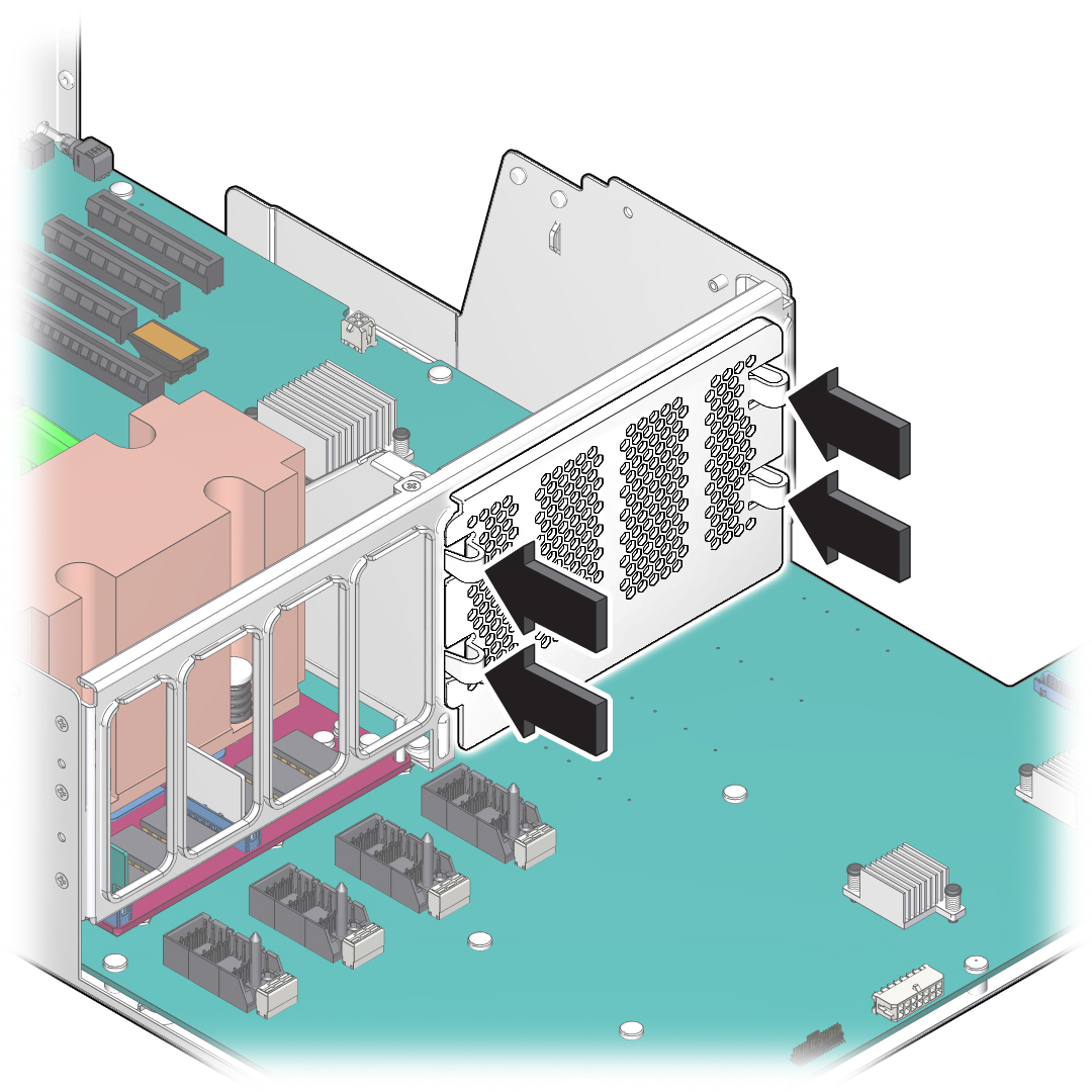
The four hoops on the airflow baffle face away from the center bracket.

- Set the lower guide in the corner of the outer unused slots.
- Press each of the four hoops
until the airflow baffle's hooks snap firmly into place.

- Verify that the airflow baffle is securely attached to the center bracket.
- On the memory riser
side of the center bracket, align the airflow baffle over the four
unused slots.
- Reinstall all memory risers.
- Install the SP that you removed
from the old motherboard.
See Install the SP.
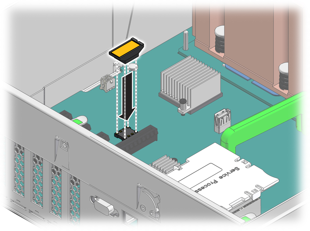
- Install the System Configuration
PROM that you removed from the old motherboard.

- Reinstall all PCIe cards.
See Install a PCIe Card or Filler Panel.
Remove all transcievers from a PCIe card before you install the card.
- Install the top cover.
- Return the server to the normal operating position.
- Reconnect the power cords to
the power supplies.
See Attach Power Cords.
- Prior to powering on the server,
connect a terminal or a terminal emulator (PC or workstation) to
the SP through the SER MGT port.
Refer to Server Installation for instructions.
The SP detects the host firmware on the replacement motherboard is not compatible with the existing service processor firmware, further action will be suspended and the following message will be displayed:
Unrecognized Chassis: This module is installed in an unknown or
unsupported chassis. You must upgrade the firmware to a newer
version that supports this chassis.
Note - Whenever you replace the motherboard or the SP, update the firmware on the server so the portions of firmware in the two components remain consistent. - Prepare to download the system
firmware.
If necessary, configure the server's NET MGT port so that it can access the network. Log in to the SP through the NET MGT port.
Refer to the Oracle ILOM documentation for network configuration instructions.
- Download the system firmware.
Follow the firmware download instructions in the Oracle ILOM documentation.
Note - You can load any supported system firmware version, including the firmware version that was installed prior to replacing the motherboard. - If necessary, reactivate any
RAID volumes that existed prior to replacing the motherboard.
If your server contained RAID volumes prior to replacing the motherboard, see Reactivate RAID Volumes for instructions.
- Power on the server.
See Power On the Server (Oracle ILOM) or Power On the Server (Power Button).
- (Optional) Transfer the serial
number and product number to the FRUID of the new motherboard.
If the replacement motherboard must have the same serial number as the server prior to servicing, trained service personnel must take this action in a special service mode.
Related Information
Oracle ILOM documentation