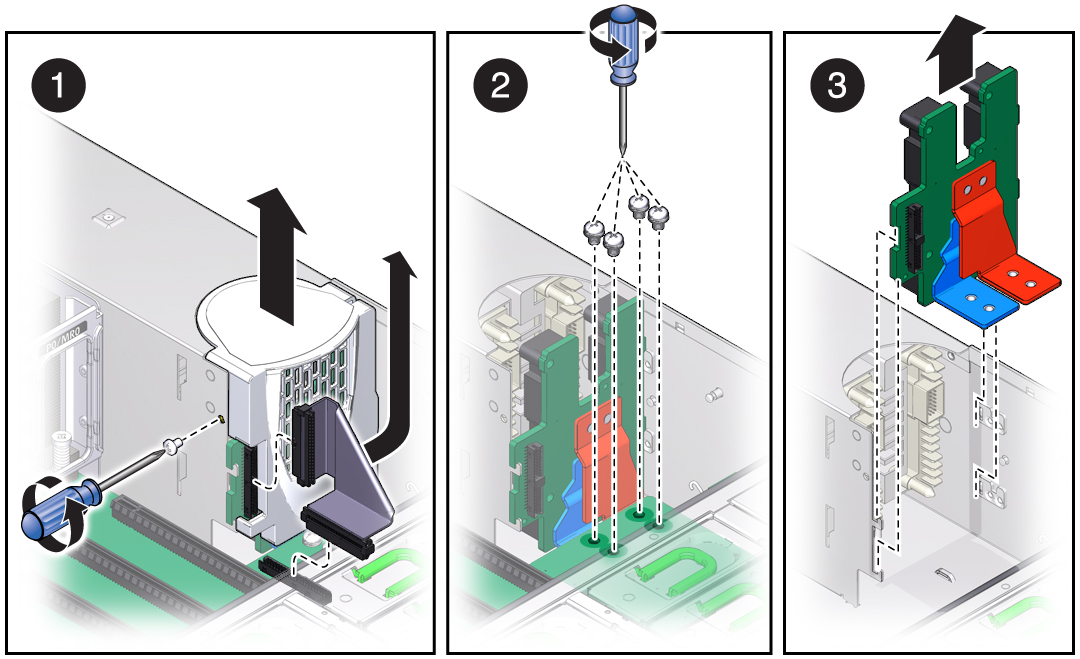
Remove the PS Backplane
 | Caution - Power is supplied to the PS backplane even when the server is powered off. To avoid personal injury or damage to the server, you must disconnect power cords before servicing the PS backplane. |
This is a cold-service procedure that must be performed by qualified service personnel. The server must be completely powered down before performing this procedure. See Component Service Categories for more information about this category of service procedures.
- Prepare
for servicing.
- Attach an antistatic wrist strap.
- Power off the server and unplug power cords from the power supplies.
- Extend the server to the maintenance position.
- Remove the top cover.
See Remove the Top Cover.
- Pull both power supplies at least part-way out of the chassis, to disconnect them from the PS backplane.
- Remove all memory risers.
- Remove the air divider by pulling it up and out of the chassis.
- Remove the ribbon cable connecting
the PS backplane to the motherboard (panel 1).

- Remove the screw that holds the PS backplane cover in place (panel 1).
- Remove the PS backplane cover
(panel 1).
You must guide two slots on the PS backplane cover around two pins on the inside of the power supply cage.
- Remove the four bus bar screws that secure the motherboard to the PS backplane.
- Disconnect the AC cables from
PS backplane.
Tilt the PS backplane to access the cable connectors.
- Lift the PS backplane out of the chassis.
- Install a new PS backplane.