Install the Fabric Interconnect F1-15
 | Caution - A minimum of two people are required to perform this installation safely. Also, make sure to measure out the locations for the Fabric Interconnect and CMA and place all the cage nuts for each before attempting to install the Fabric Interconnect. Failure to install all the cage nuts for the Fabric Interconnect and CMA before the Fabric Interconnect is in place can prevent you from installing the CMA's cage nuts in the correct location. |
- Select the location in the rack where the Fabric Interconnect will be installed.
- Make sure that at least one rack unit of space exists below the location where the Fabric Interconnect will be installed.
- Choose the correct mounting screws for your rack. The Fabric Interconnect is shipped with three complete sets of mounting screws (10-32, 12-24 and M6), which support a wide variety of common equipment racks.
- If you are using an untapped rack, for example a Sun/Oracle rack, insert the M6 cage nuts now if you have not already done so. Later in the procedure, you will then use M6 screws to secure the chassis to the rack.
- Mark each of the rack posts at the locations that will correspond to the bottom of the Fabric Interconnect when it is installed. Verify that all four marks are level. This mark also indicates the top of the rail kit.
-
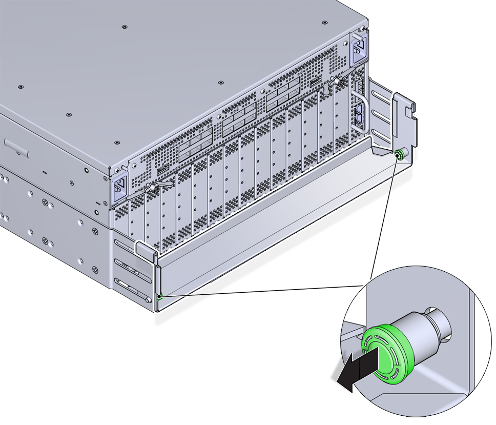
Inside the module retention bracket, locate the two spring-loaded pins as
shown in Module Retention Bracket's Compression Pins.
Figure 5 Module Retention Bracket's Compression Pins
-
Simultaneously pull the two pins inward (toward each other), and slide the
module retention bracket off of the Fabric Interconnect chassis. See Removing the Module Retention Bracket.
Figure 6 Removing the Module Retention Bracket
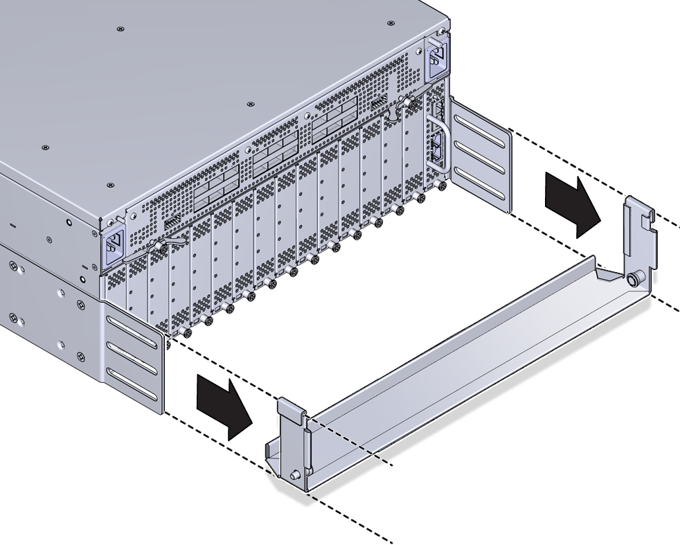
Note - The module retention bracket is used to hold modules and blanks in place while the product is in transit. After removing the module retention bracket, keep it for future use. - If you have not already done so, you must determine the depth of the rack to determine where to attache the side panels to the chassis.
- Align the side panels with screw holes at the I/O-module end of the chassis, and insert 4 flat-head screws through the side panels into the screw holes in the chassis.
- Align the mounting brackets with the screw holes in the fan-unit end of the chassis, and insert 4 flat-head screws through each mounting bracket into the screw holes in the chassis.
-
Using the flat-head screws, attach the side panels (4 screws per side
panel) and mounting brackets (4 screws per bracket) to the Fabric
Interconnect. Installing the Mounting Brackets and Side Panels shows installing these components.
Use four (4) 10-32 x .25” Phillips flat-head screws per bracket
Figure 7 Installing the Mounting Brackets and Side Panels
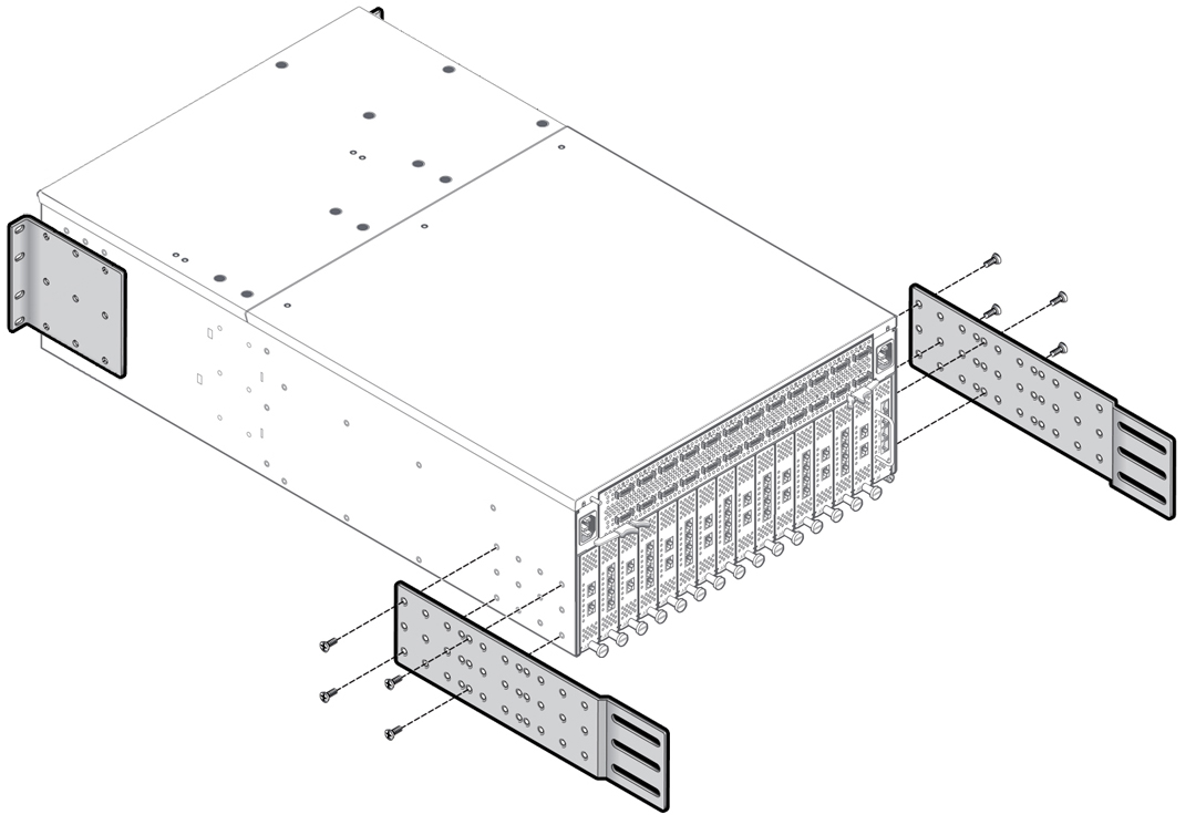
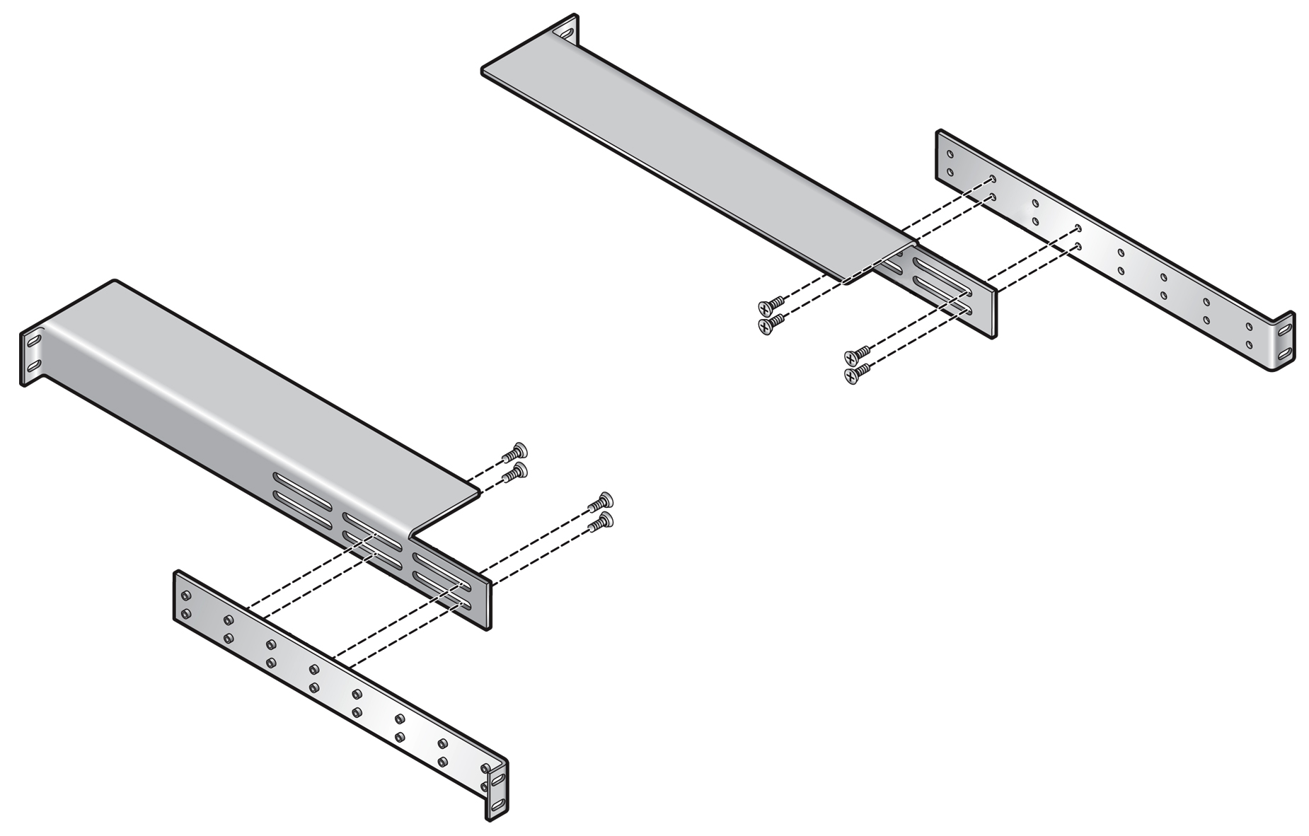
Note - Depending on your order, the brackets (long rails) shown in Installing the Mounting Brackets and Side Panels might already be installed. This procedure documents installing these parts for completeness in case they are not already installed when you remove the Fabric Interconnect from the shipping container. - Align the rack mount rails with the slotted piece inside the piece with the standoffs. Leave some overlap between the ends of each piece.
-
From the bags of screws that came with the rack mount rails, insert the
10-32 x .25” pan-head screws (4 per rail) through the slotted rail
piece into the piece with the threaded standoff. Do not completely tighten
the screws. You want to leave some slack in the rails so that they can slide
lengthwise to accommodate the depth of the rack. Assembling the Rack Mount Rails shows assembling the rack mount
rails.
Use short pan-head screws (10-32 x .25”) from the rail kit box.
Note - The rack mount rails have 3 slots. Assembling the Rack Mount Rails shows the rails being assembled through an end slot and a middle slot. For deeper racks, you can use the end slots to lengthen the rack mount rails as needed.Figure 8 Assembling the Rack Mount Rails
- Repeat Step 12 and Step 13 to assemble the second rack mount rail.
-
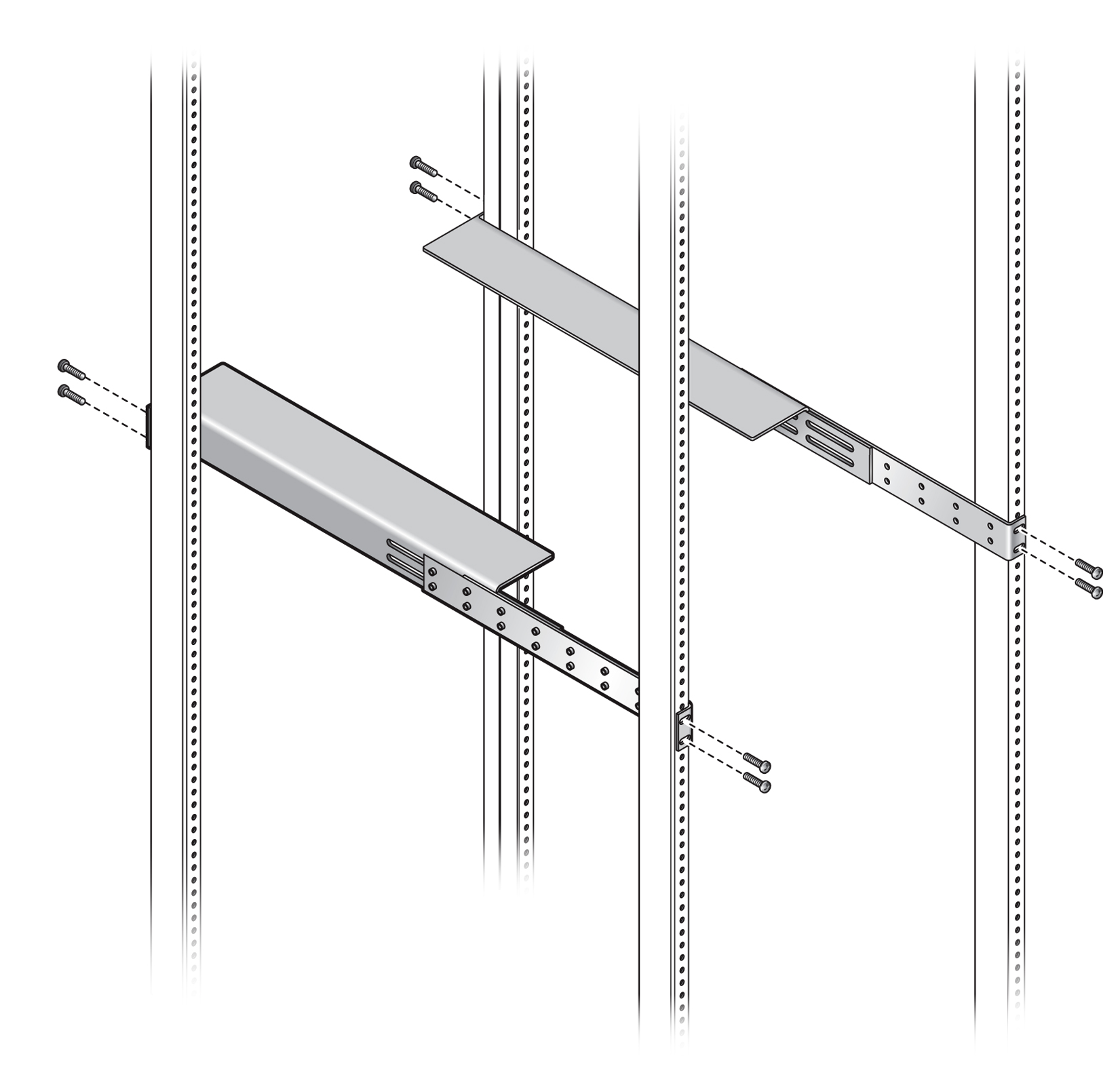
When both rails are assembled, use the 10-24, 10-32, of M6 pan-head screws
(4 screws per rail) from the rack mount box to install rails into the rack
as shown in Installing Assembled Rack Mount Rails into Equipment Rack. Because you did not completely
tighten the screws when you assembled the rails, you should be able to slide
the rails lengthwise to accommodate the depth of the rack.
Note - If you are installing into a rack tapped for 12-24 screws, you must use the accompanying #12 lock washers. For 12-24 racks, insert the screw into the lock washer before installing the screw into the rack.Use four (4) long screws from the rail kit box to attach each mounting rail to the rack. Use the appropriate screw for your type of rack:
-
10-32 x .375” Phillips pan-head screws
-
12-24 x .5” Phillips pan-head screws with lock washer already attached to the screw
-
M6 x 16 mm Phillips pan-head screws
Figure 9 Installing Assembled Rack Mount Rails into Equipment Rack
-
-
When the rails are attached to the rack posts, tighten all screws that
connect the pieces of the rail, as well as the screws that attach each
assembled rail to the rack.

Caution - All screws that assemble the rails and attach the rails to the rack must be tightened before resting the chassis on the rails.
- Load the chassis into the rack so that the I/O-module side is supported on the horizontal surface of the rails. See Installing Assembled Rack Mount Rails into Equipment Rack for the horizontal surface of the rails.
-
Begin sliding the chassis into the rack on the horizontal surface created
by the rails. Inserting the Fabric Interconnect F1-15 into the Equipment Rack shows inserting the chassis into
the rack.
Figure 10 Inserting the Fabric Interconnect F1-15 into the Equipment Rack
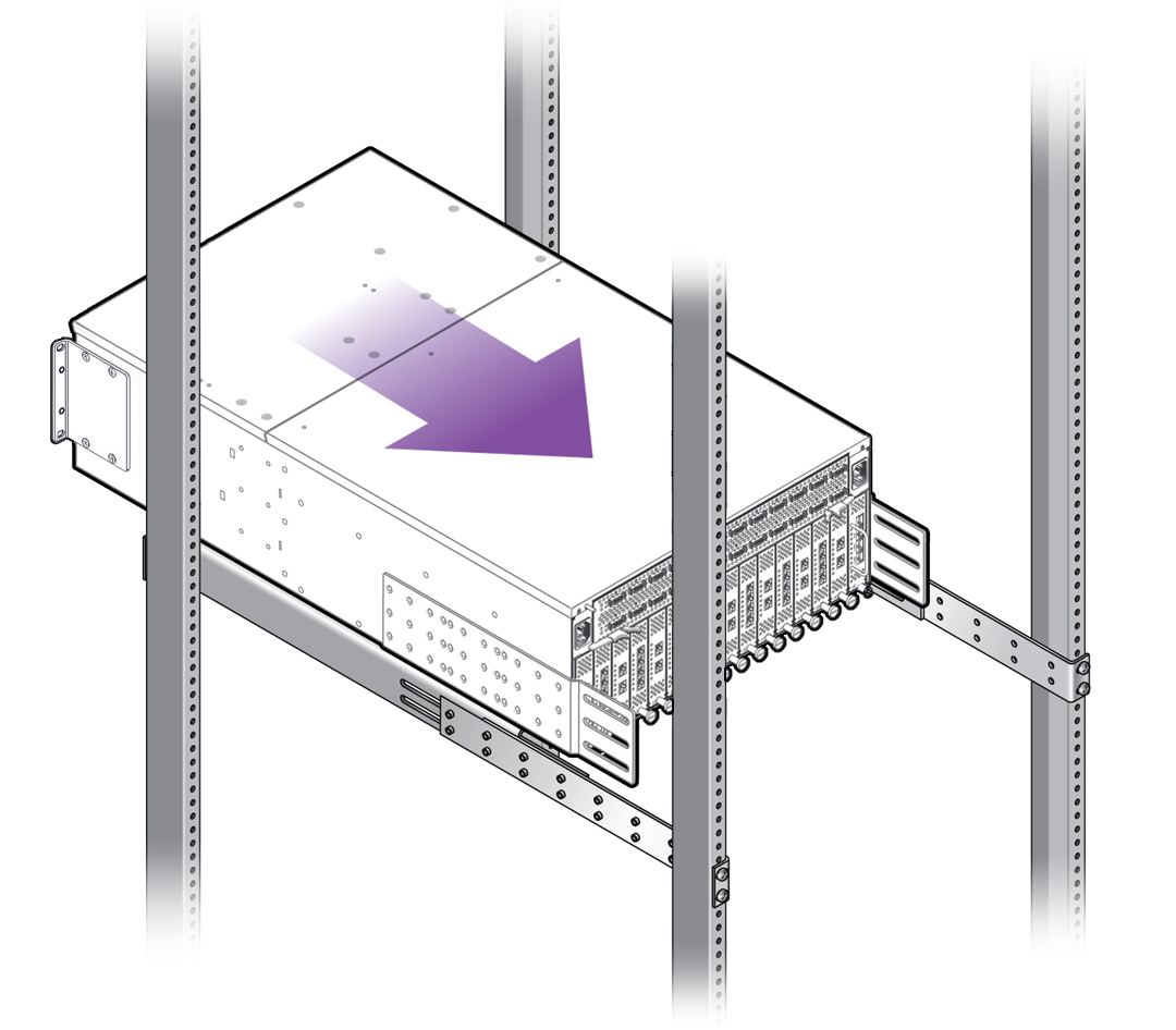
Note - Inserting the Fabric Interconnect F1-15 into the Equipment Rack shows installing the Fabric Interconnect from the rear of the rack. Whether you install back-to-front, as shown, or front-to-back is irrelevant as long as the chassis is inserted so that it is supported on the horizontal surface of the rails. The horizontal surface is required to support the Fabric Interconnect as it slides into the rack. - Continue to slide the Fabric Interconnect into the rack until the mounting brackets contact the vertical rack post. The chassis is completely inserted into the rack when the mounting brackets lie flush against the vertical rack post.
- When the chassis can no longer slide into the rack, insert the pan-head screws through the mounting brackets on the fan-unit side of the chassis, and tighten them to secure the chassis to the rack posts. In this example, the rear mounting brackets will secure the chassis to the rear rack posts.
- Choose either of the following workflows based on whether you have a standard 4-post rack or a 27” Sun/Oracle rack: