Connect the 4-Port 10 GE Module to Other Equipment
The 4-Port 10 GE module can be connected to network equipment through different methods, which are determined by the type of cables and connectors you ordered.
If you are using SFP+ passive or active copper cables, the port transceivers are integrated into the cable. With the transceiver already present on the cable, you will insert one end of the cable into the I/O Module and the other end into a 10 Gbps-capable port on the peer device.
If you are using the SFP+ optical transceivers, you will need to connect both the transceiver and cable. The following procedure documents using the standalone SFP+ optical transceivers, which is the more involved procedure.
To connect the 4-Port 10 GE Module using SFP+ optical transceivers, follow this procedure:
- Insert the 4-Port 10 GE Module into the Fabric Interconnect, and allow it to power on.
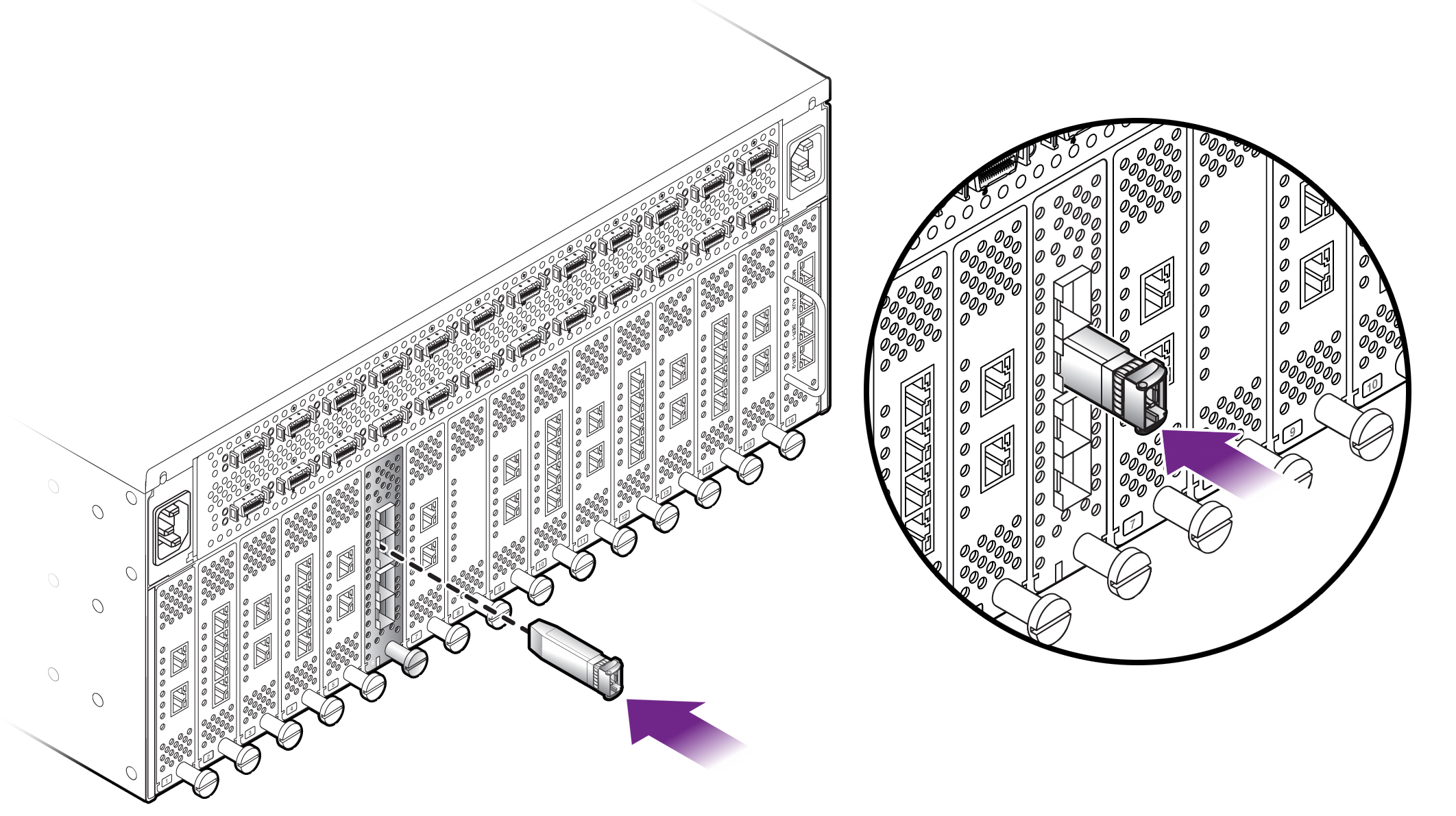
- Align the optical transceiver with the port cage on the I/O Module. The transceiver is keyed so that it can only be inserted in the correct orientation.
- When the module has completely
booted, insert the SFP+ optical transceiver into the port cage on
the
4-Port 10 GE module. See Inserting the Optical Transceiver into the 4-Port 10 GE Module.
Note - Make sure that the optical transceiver is fully inserted, and make sure that the transceiver's handle lies flush with the face of the transceiver. If the handle does not lie flush, it can interfere with inserting or removing the cable.Figure 53 Inserting the Optical Transceiver into the 4-Port 10 GE Module

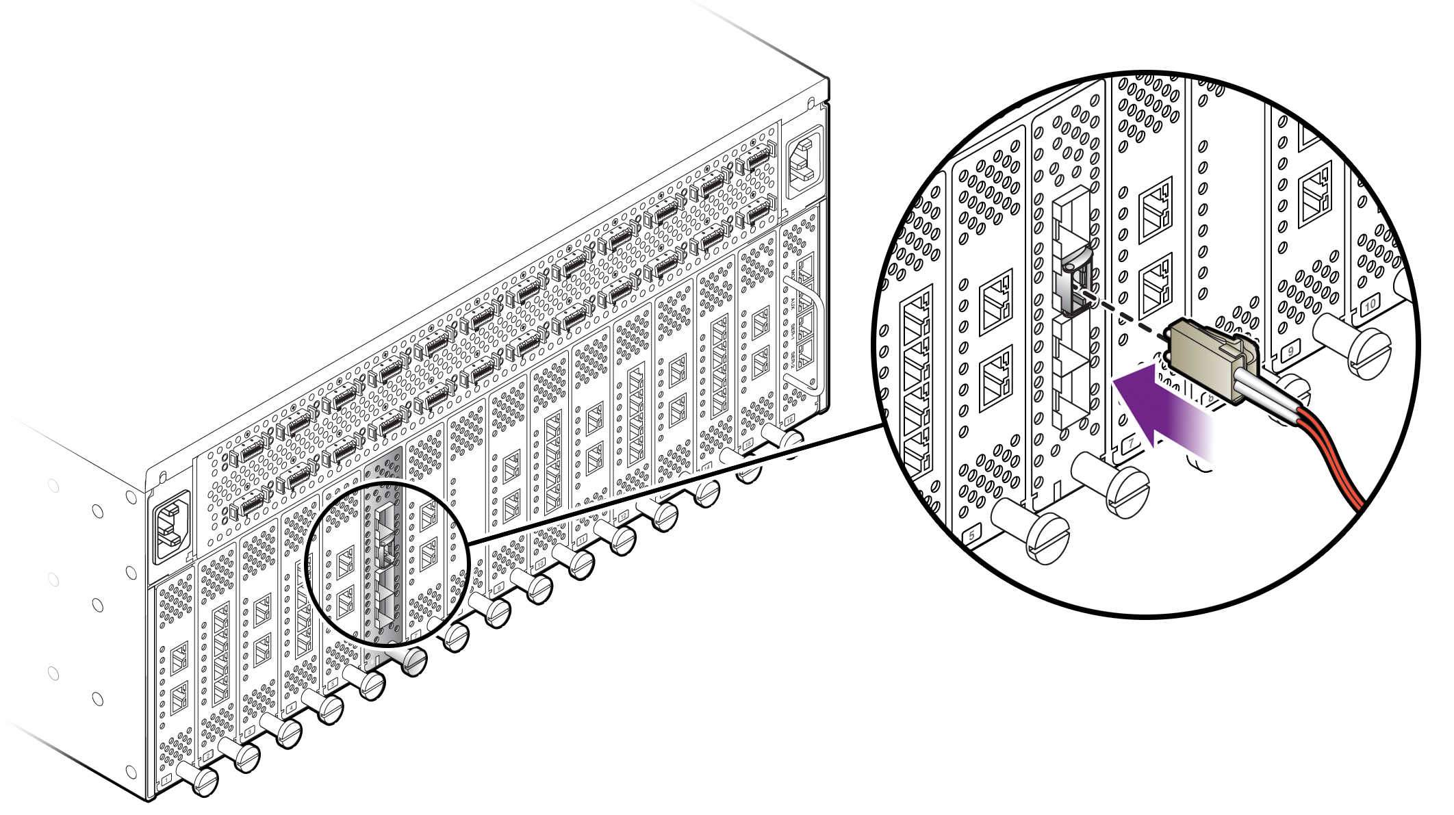
- Insert one end of the optical
cable into the SFP+ transceiver. See Inserting the Optical Cable into the Optical Transceiver.
Figure 54 Inserting the Optical Cable into the Optical Transceiver

- Connect the other end of the cable to a 10 Gbps port on a peer device, such as a 10 Gbps Ethernet switch.
- Check the Link LED on the 4-Port 10 GE module's port to make sure that the port detects the cable. The Link LED should be glowing steady green.
- Check the Link LED on the peer device. The Link LED on the peer device should show that a physical link has been successfully established.
- Check the Activity LED. If traffic is being transmitted or received between the 4-Port 10 GE Module and the peer device, the Activity LED blink amber whenever traffic is detected on the link.