Install the CMA
To install the CMA, follow this procedure:
- Using tape or a marker, make two horizontal marks, one on each of two rack posts. These marks must be level because they will indicate where the CMA will be attached to the rack.
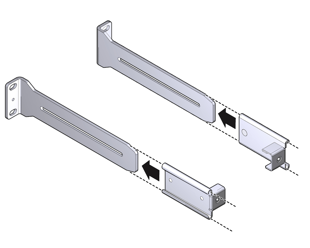
- Slide the attachment bracket
over the extender, so that the tab on the bracket is opposite the
flange on the extender as shown in Attachment Bracket sliding over the Long Rail.
The open end of the tab is toward the flange. The flat end of the tab is toward the rear of the extender.
Figure 16 Attachment Bracket sliding over the Long Rail
- Place the attachment plate on the flange side of the extender, opposite the attachment bracket.
- Use two M4 screws to sandwich
the attachment bracket and plate to the extender, in the position
farthest from the flange as shown in Bracket and Plate Sandwiching to the Rail.
Figure 17 Bracket and Plate Sandwiching to the Rail
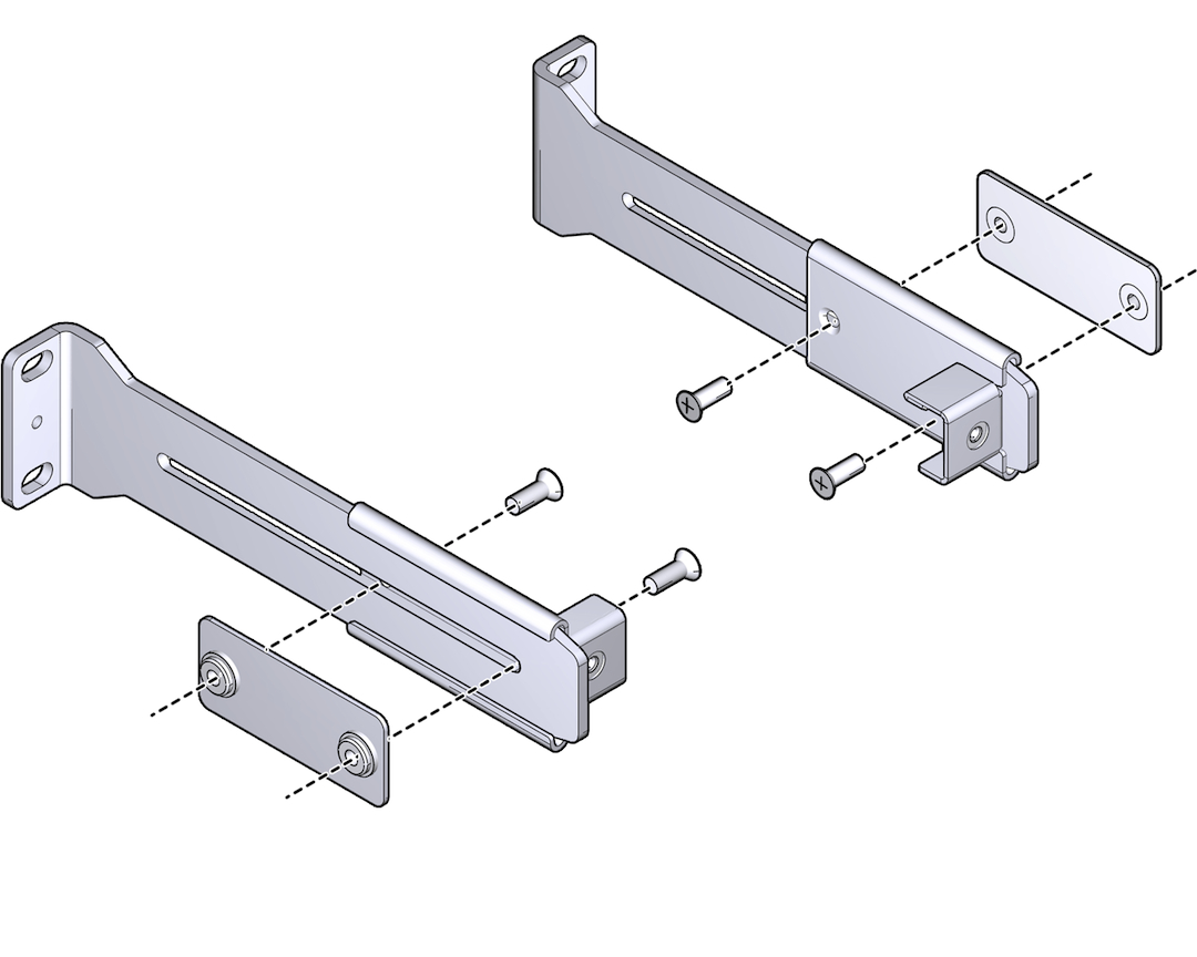
- Using a No. 2 Phillips screwdriver, tighten the two screws.
- Repeat Step 2 through Step 5 for the other cable management extender.
- Place the long rail to the mounting
location (see Step 1) on the post of the rack. Make
sure that these rails are flush with the side of the Fabric Interconnect chassis,
with the flange pointing outward as shown in front brackets being installed.
Figure 18 front brackets being installed
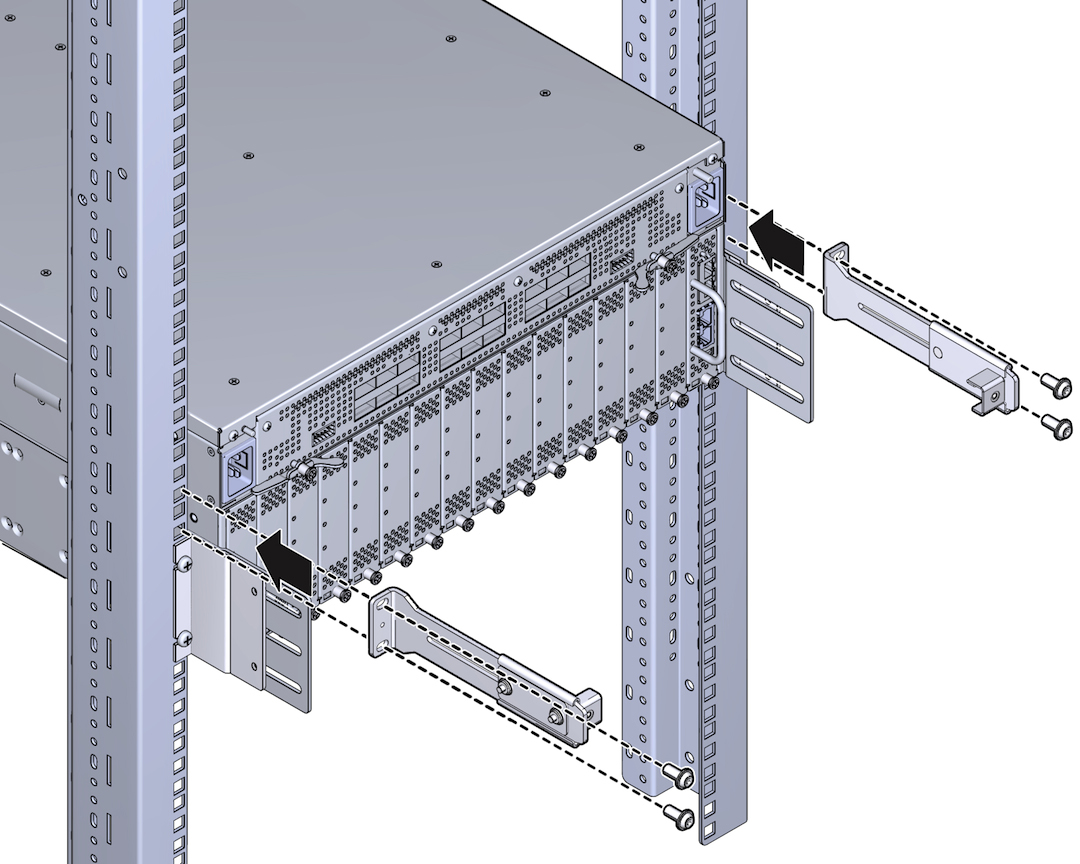
- Secure the assembly to the post
with the correct screw type for the rack (10-32, 12-24, or M6) by
inserting the screw through the slotted end of the CMA and into
the rack or cage nut.
Note - If you are installing into a rack tapped for 12-24 screws, you must use the accompanying #12 lock washers. For 12-24 racks, insert the screw into the lock washer before installing the screw into the rack. - Repeat Step 7 to Step 8 for the other cable management extender and long rail.
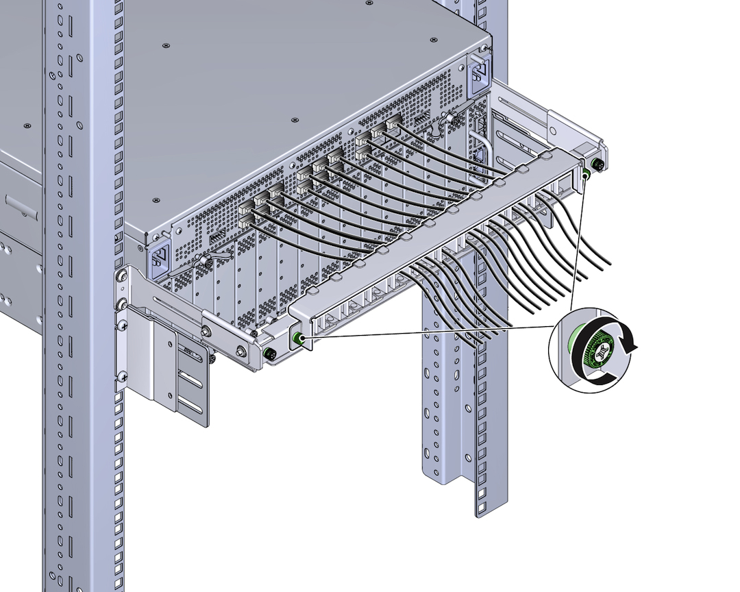
- If needed, disassemble the CMA comb and plate by loosening the green captive screws.
- Align the green captive screws
in the comb with the two screw holes in the tabs as shown in Installing the CMA's Comb.
Figure 19 Installing the CMA's Comb
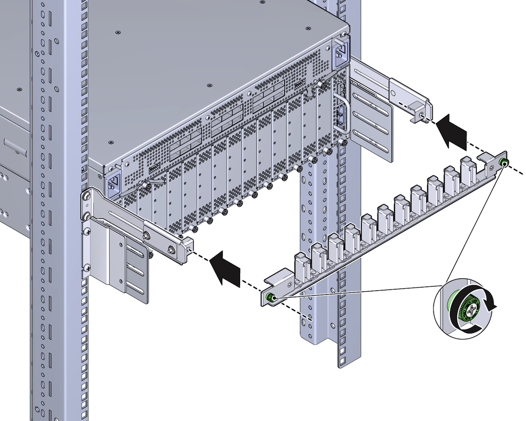
- Using a Phillips-head screwdriver, tighten the green captive screws to attach the comb to the standoffs.
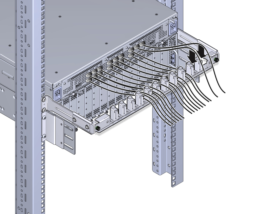
- When the CMA's comb is installed,
connect cables and drape them into the slots in the comb as shown
in Connecting Cables and Draping Them Through the Comb.
Note - Make sure not to exceed the allowed bend radius for any cables you route through the comb. Also, wherever possible, make sure to drape equal numbers of cables in each slot to apply the cable weight equally along the CMA.Figure 20 Connecting Cables and Draping Them Through the Comb
- When all cables are connected,
align the captive screws in the top of the CMA with the screw holes
in the CMA's comb as shown in Installing the Top of the CMA.
Figure 21 Installing the Top of the CMA
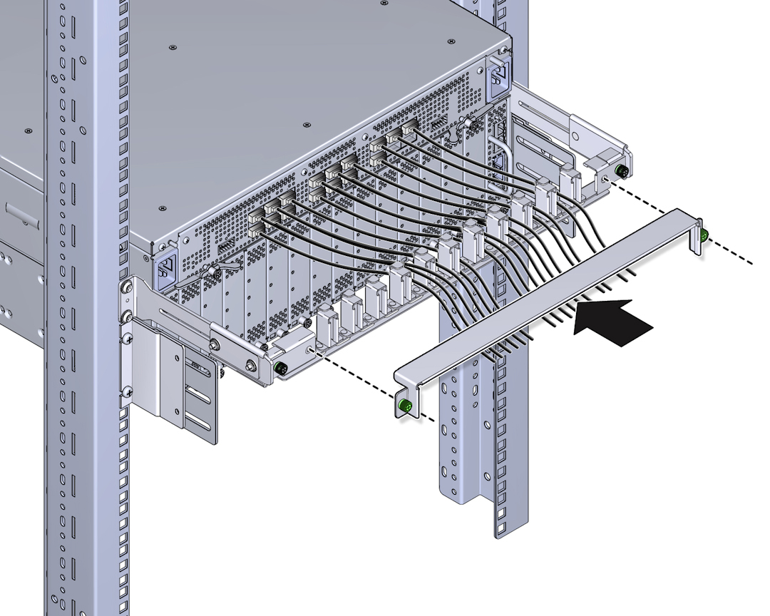
- Using a Phillips-head screwdriver,
tighten the screws to secure the plate to the comb as shown in Completing Assembly of the CMA.
Figure 22 Completing Assembly of the CMA
